42
Selectronic Australia
Rev 41 - Dec 2022
Operation
Operation
Controls and Indicators
User Interface
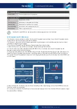
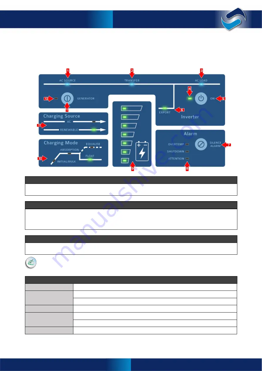
This section lists the controls and indicators found on the front panel of the SP PRO. The indicator brightness
is adjusted according to the ambient light conditions (blue LEDs excepted).
1 – AC Source*
When illuminated, this shows the presence of AC supply voltage from either the mains grid or backup generator (when
installed), whichever is applicable. This is powered directly from the incoming AC supply.
2 – Transfer*
Illuminated when an external AC supply is connected through to the AC Load output. If AC Source is illuminated but
Transfer is not, it would generally indicate that the AC supply is out of sync tolerance – either the voltage or the
frequency is beyond the set limits. It is normal operation for this to flicker slightly. This LED is always off with an
external AC Source contactor.
3 – AC Load*
When illuminated, this shows the presence of AC voltage ready to supply site loads. This is powered directly from the
inverter AC output or AC supply.
*Indicators
1,2,3
will operate without any DC connection to the SP PRO. An external AC supply will
activate the AC bypass and illuminate these indicators.
4 – Output Mode Status
Off
SP PRO battery supply disconnected. AC bypass only.
Slow Flashing Yellow
SP PRO is idle (off) – Monitoring and logging but no inverter AC output.
Steady Green
The SP PRO is on.
Fast Flashing Green
SP PRO is preparing to start.
Steady Red
A fault has been detected and no inverter output is possible.
Flashing Red
Open circuit or poor battery connection and no inverter output is possible.
Slow Flashing Red
Inverter has not been configured using SP LINK. No inverter output is possible.
Controls and Indicators
Содержание SPPRO 2i Series
Страница 1: ......
Страница 2: ...Selectronic Australia 2023 ...
Страница 51: ...47 Selectronic Australia Rev 41 Dec 2022 Operation SP PRO Operation ...
Страница 64: ...Contents Doc O10003 Part 004122 Rev 41 Dec 2022 ...


