40
Selectronic Australia
Rev 41 - Dec 2022
Installation
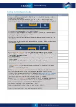
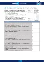
Checking Generic AC Coupled Systems
For systems incorporating Generic AC Coupling, the following items should be verified.
on page 35 should be completed first.
IN0034 – SP PRO Generic AC Coupling installation notes
and ensure the system has been installed and commissioned according to
this document before completing the following checklist.
•
Turn on the DC supply to the SP PRO(s). Long press the ON button so that only the
blue AC Load LED is lit.
•
Connect SP LINK to the SP PRO inverter(s).
•
Connect the AC supply to the grid feed inverter(s).
•
Turn on the PV supply to the grid feed inverter(s) and let the battery charge from the grid feed inverter(s)
until it reaches the charge target voltage. The charge target voltage is shown in SP LINK >
Data View
>
Technical Data
>
Target Charge Voltage
Item to Check
Result
When voltage goes above battery charge target, check that the AC Load frequency ramps to
55.2Hz (no system Load, generic inverter is charging).
When the AC Load frequency ramps to 55.2Hz, check that the output from the solar inverters
drops to zero and the battery voltage falls.
Check that the AC Load frequency drops back to 50Hz when the battery voltage falls below
the charge target voltage.
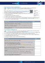
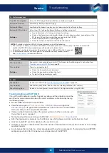
Checking DC Coupled Systems
For systems incorporating DC Coupled renewable energy, the following items should be verified.
on page 35 should be completed first.
Refer to relevant document(s) referred to in
DC Couple Charge Controller Preparation
on page 25 and
ensure the system has first been installed and commissioned according to these document(s).
•
Turn on the DC supply to the SP PRO. Long press the ON button so that only the blue AC Load LED is lit.
•
Connect SP LINK to the SP PRO inverter.
•
Disconnect the battery supply to the DC charge controller(s).
Item to Check
Result
Record the name for shunt 1 and 2 (Solar, Wind, Hydro).
1
2
Read the Solar (or Wind or Hydro) Shunt 1 current in >
Data View
>
Now
>
Solar (Wind or Hydro)
Shunt 1.
Current should be zero or very close (<0.2A).
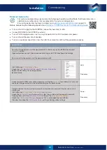
Repeat for shunt 2 (if connected) and record the results.
If a shunt reading is not zero, then in SP LINK >
Service Settings
>
Zero Shunt 1
or
Service Settings
>
Zero Shunt 2
1
2
Connect the renewables and battery to the DC charge controller(s).
Measure the DC charge current(s) with a DC clamp meter and compare this with the Shunt 1 current.
Repeat for shunt 2 (if connected). Record results.
1
2
Let the battery charge from the renewables until Float charge stage is reached on the DC charge
controller.
Check the front panel of the SP PRO to see that its charging mode has dropped to Float.
Put a Load on the system until both the SP PRO and the charge controller drop out of Float.
Turn off the Load and let the battery charge back to Float.
Again, check that the SP PRO has dropped to Float.
Commissioning
Содержание SPPRO 2i Series
Страница 1: ......
Страница 2: ...Selectronic Australia 2023 ...
Страница 51: ...47 Selectronic Australia Rev 41 Dec 2022 Operation SP PRO Operation ...
Страница 64: ...Contents Doc O10003 Part 004122 Rev 41 Dec 2022 ...


