38
Selectronic Australia
Rev 41 - Dec 2022
Installation
Continue Common System Checks
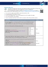
Item to check
Result
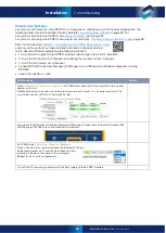
Turn on the AC Source input to the SP PRO(s).
Do not
turn on the DC battery supply or the pre-
charge / Battery Sense supply.
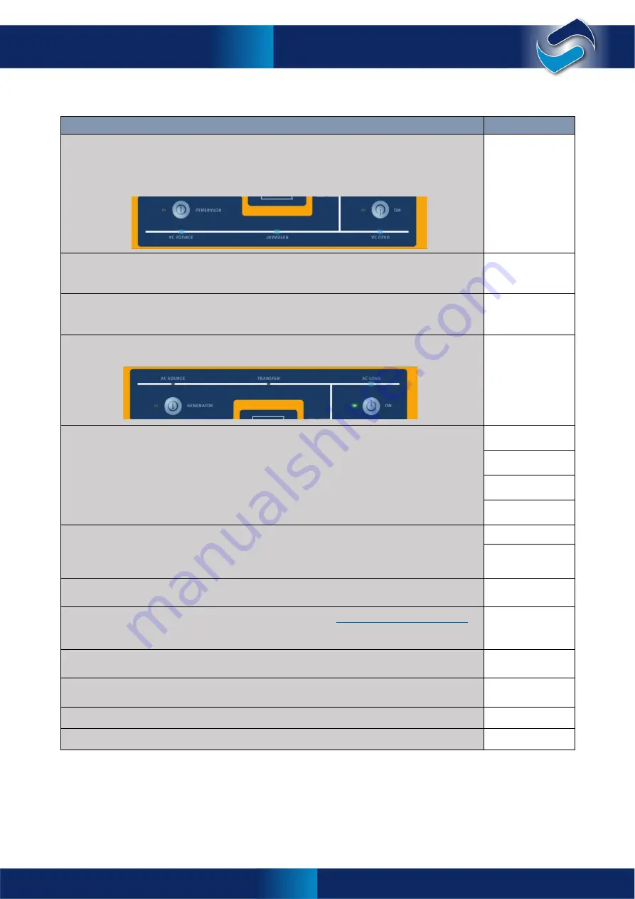
Three blue LEDs will light up on each phase manager. AC Source, transfer and AC Load.
Note that if you have installed an external AC Source contactor, the transfer LED won’t light up.
•
Turn OFF AC Source and check that AC Load is turned OFF.
•
Turn ON pre-charge / Battery Sense breaker or fuses. After ten seconds all the LEDs light up
red then green before settling to normal display.
•
Turn ON main DC breaker or fuses.
•
Run SP LINK on a Windows computer and connect to the System Manager (L1 Manager) via
the USB port.
Do a long press on the ON button on System Manager (L1 Manager). The blue AC Load led will
light on each SP PRO.
In >
Data View
>
Technical Data
>
L1 Manager
read the following for the System Manager:
•
Sense Voltage – should be equal to the DC Inverter Voltage reading. Both should be equal to
the voltage at the battery terminals.
•
DC Inverter Voltage.
•
Midpoint Voltage (where mid point is connected, otherwise ignore) – should be half the
Sense Voltage.
•
Midpoint Error – should be <5% unless battery bank needs to be equalised.
•
Put a Load on the system.
In >
Data View
>
Now
> in the System Manager (L1 Manager) read and record the Battery
Current.
•
Also read and record Battery Voltage.
Back in >
Data View
>
Technical Data
read and record the Cable Loss (L1). Cable Loss should
be <1% of Load power for 24V system, <0.5% of Load power for 48V and 120V systems.
Check the battery temperature sensor is installed according to
Battery Wiring (DC) Preparation
on page 18. Check temperature sensor is only connected to System Manager (L1 Manager)
(Temperature sensor is not required when managed batteries are installed).
Back in >
Data View
>
Technical Data
read and record the Battery Temperature. Check that this
is correct. With managed batteries this is read directly from the BMS via the CAN bus.
Activate all used digital inputs and check for >10VDC but <60VDC.
Deactivate all used digital inputs and check they are <3VDC.
Activate all used Relay Outputs and check the relay current is <0.5A DC.
Activate all used Digital Outputs and check the current is <5mA DC.
Commissioning
Содержание SPPRO 2i Series
Страница 1: ......
Страница 2: ...Selectronic Australia 2023 ...
Страница 51: ...47 Selectronic Australia Rev 41 Dec 2022 Operation SP PRO Operation ...
Страница 64: ...Contents Doc O10003 Part 004122 Rev 41 Dec 2022 ...

