31
Selectronic Australia
Rev 41 - Dec 2022
Installation
Communications
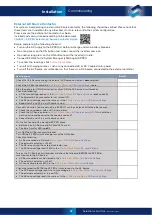
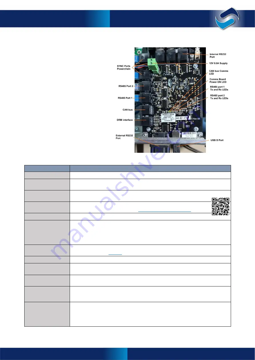
Communications Port Functions
Overview
All SP PRO series 2i inverters come standard
with a number of communications interfaces
for connection to external system
components. To further enhance the
capability of the SP PRO, a number of
optional communication devices are
available.
Port Name
Port Function
Sync Ports (RJ45)
SYNC 1 and SYNC 2 ports are used for inter-inverter communications in Powerchain.
RS485 Port 2
(RJ45)
Used to communicate with up to five Selectronic Certified (SCERT) solar inverters in a
Managed AC Coupled system (see ‘Managed AC Coupled Preparation’).
RS485 Port 1
(RJ45)
Used to communicate with managed batteries that use Modbus over RS485 or to read and
write Modbus commands to the SP PRO. Contact Selectronic for details.
CAN bus (RJ45)
Communication with managed batteries that use CAN bus communications.
For a list of compatible batteries go to
Selectronic Approved Batteries
DRM Interface
RJ45 interface provides all the DRM functions as outlined in AS/NZS 4777.2:2020.
Internal RS232 Port
(RJ45); and External
RS232 Port (DB9)
There is only one RS232 port in the SP PRO series 2i, which can be configured to come
from either the External RS232 (DB9) port or the Internal RS232 port (RJ45). Decide which
connection is most convenient for your installation then configure the SP PRO accordingly.
The default configuration is the External RS232 port (DB9). See Appendix A –
Specifications for RS232 pinouts.
USB B Port
(USB type B)
Provides USB communications with the Windows computer running SP LINK via the
supplied USB cable.
software is free and an available link is on page 2
12V 0.8A Supply
User power supply to operate external devices. Rated at 12V 0.8A max.
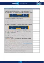
CAN bus Comms LED
Flashes when CAN bus communications is operating correctly on managed batteries. On
constantly when there is problem with CAN bus communications or when it is not used.
Comms Card Power
On LED
On constantly when the Communications Card is powered up and functioning.
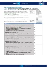
RS485 Port 1 Tx and
Rx LEDs
Shows the status of the RS485 port 1 transmit (Tx) and receive (Rx) signals. Tx will flash
when the SP PRO is sending data to the port. Rx will flash when data is being received from
the port.
RS485 Port 2 Tx
and Rx LEDs
As above but for RS485 port 2. When Managed AC Coupled is configured correctly, both
the Tx and Rx LEDs will flash. When only the Tx LED is flashing, the SP PRO is
communicating correctly and there is a problem external to the SP PRO. Check the
communications cables to, and the connections and configuration of the Selectronic
Certified solar inverter (SCERT).
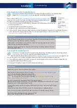
Ancillary Components
Содержание SPPRO 2i Series
Страница 1: ......
Страница 2: ...Selectronic Australia 2023 ...
Страница 51: ...47 Selectronic Australia Rev 41 Dec 2022 Operation SP PRO Operation ...
Страница 64: ...Contents Doc O10003 Part 004122 Rev 41 Dec 2022 ...

