RECOMMENDED TOOLS
1
Channel Locks
2
Adjustable Wrench
3
Plumbers' Putty or Caulking
4
Phillips Screwdriver
5
Flat Blade Screwdriver
6
Electric Drill & 1/4" Drill Bit
7
Tape Measure
1
2
3
4
5
6
7
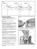
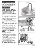
INSTALL SPOUT ASSEMBLY;
Fig. 1
INSTALLATION
CAUTION
Turn off hot and cold water
supplies before beginning
10'
1
114mm
(4-1/2)
500mm
(20")
413mm
(16-1/4)
FINISHED
WALL
32mm
(1-1/4) DIA.
125mm
(4-7/8)
60mm
(2-3/8) MAX.
MOUNTING
SURFACE
(243mm)
9-9/16"
(127mm)
5"
(133mm)
5-1/4"
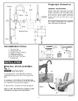
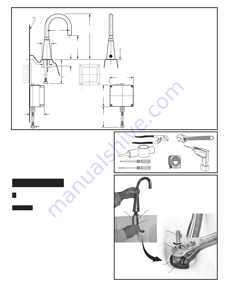
Roughing-in Dimensions
GENERAL DESCRIPTION:
Electronic faucet with proximity operation. Vandal
resistant solid brass construction single post
mounting. Operates on AC permanent power.
In-line strainer for solenoid is integral. Single inlet
3/8 compression, built-in checks, and flexible
stainless steel 16-1/4" reach inlet hose for spout
connection.
Note: All plumbing and electrical wiring must
be installed in accordance with applicable
codes, regulations and standards.
1.
Insert WIRES
(1)
, FLEX HOSE
(2)
and SPOUT
SHANK
(3)
through center hole of mounting surface.
Fig. 1.
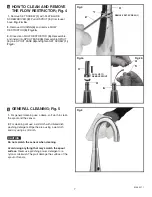
2.
Assemble "C" WASHER
(4)
, STAR WASHER
(5)
and LOCKNUT
(6)
onto threads of SPOUT SHANK
(3)
from underside of mounting surface.
Fig. 1a.
3.
Align FAUCET and tighten LOCKNUT
(6)
.
Fig. 1a.
Note: 4" and 8" Deck Plates are available for other
installations, see page one for information.
Fig. 1a
Fig. 1
2
M 9 6 5 2 7 1
1
2
3
4
5
6
3
3/8" COMP.
81mm
(3-3/16)
(53mm)
2-1/8" DIA.
ELECTRICAL BOX OR
EQUIVALENT BY OTHERS

