background image

%

BIESSE S.p.A. Woodworking Machinery
(l110h046.fm-141101)

$SSHQGL[%

7HFKQLFDO&KDUDFWHULVWLFV

%

1RLVH/HYHO

Sound pressure data are as follows:

Tests were carried out in accordance with ISO 3746 and ISO 11202 Regulations.

The noise levels given here are emission levels and do not necessarily represent safe working
levels. In spite of the existence of a relationship between emission levels and exposure levels, this
cannot be used reliably to establish whether or not other precautions are necessary. The factors
that determine the levels to which the workforce is exposed include: the length of the exposure, the
characteristics of the workplace environment, other sources of dust, noise, etc.; that is, the number
of machines and other processes in adjacent areas. In any case, this information allows the
machine user to be able to carry out a better evaluation of risks or danger.

%

'XVW(PLVVLRQ

The machine has passed the test for dust emission from woodworking machinery. This test is
carried out in accordance with the standard DIN 33893. The amount of dust issued into the
environment was less than 2 mg/m

3

. The certificate was issued by the FPH body on 10-09-2001

(reference FPH-AZ 010/2001).

Equivalent sound pressure level in position in the work area during 
machining (L

pA

)

dB(A)

 79.1

Environmental correction factor (K)

dB(A)

1.4

Sound power level during machining
(L

wA

)

(wA)

dB(A)

mW

98.6

7.2

Weighted peak instantaneous sound pressure in the work area 
during machining

dB(C)

104<130

Содержание EB 70

Страница 1: ...1859 99 Serial number 0 1 86 5 6 0 18 1 3DQHO 6L LQJ HQWUH L5801L0015 ENGLISH Issue Revision 1 0 ...

Страница 2: ......

Страница 3: ...afe place in order to have it always to hand for consultation The manual must only be used by personnel who have been adequately trained to operate the machine BIESSE cannot be considered responsible or liable for damage resulting from incorrect or improper use of the documentation provided In order to avoid incorrect manoeuvres that might result in danger to the operator or to third parties it is...

Страница 4: ... QIRUPDWLRQ RQ WKLV SXEOLFDWLRQ BIESSE S p A Woodworking Machinery l5801l0015 fm 141101 ...

Страница 5: ...OV 2 1 Rear Collet Stop for Pieces With Projecting Facings 2 2 Scoring Blade for Postformed Pieces 2 3 Cutting Area Laser 2 4 Grooving Device 2 5 Air Jet Panel Supports 2 6 Right hand Side Machine 2 7 Stop for Cuts of Variable Angular Direction analog 2 8 Stop for Cuts of Variable Angular Direction digital 2 9 Regulator of the Side Pusher Stroke 2 10 Side Pusher with Front Roller 2 11 Electronic R...

Страница 6: ...ies of Cutting Patterns Making Cuts for Square shaped Openings optional Groove Execution 6 2 Machining Hold 6 3 Piece Loading Part 3 Operations KDSWHU 0DLQWHQDQFH 7 1 Maintenance Intervention Summary and Frequency 7 2 General Cleaning of the Machine 7 3 Draining Condensate from the FR Unit 7 4 Cleaning the Filters of the Control Panel 7 5 Cleaning the Electrical Cabinet Filter 7 6 Cleaning the Air...

Страница 7: ...B 2 Blades B 3 Noise Level B 4 Dust Emission SSHQGL 7UDQVSRUW DQG QVWDOODWLRQ C 1 Machine Parts To Be Transported C 2 Unloading the Machine Lifting C 3 Shifting C 4 Machine Configuration Connection Points and Overall Dimensions C 5 Installation Area Requirements Electric System Requirements Pneumatic System Requirements Suction System Requirements SSHQGL HFRPPLVVLRQLQJ HPROLWLRQ SSHQGL XDUDQWHH DQ...

Страница 8: ... 7DEOH RI FRQWHQWV BIESSE S p A Woodworking Machinery l5801l0015TOC fm 141101 ...

Страница 9: ... used to order components that must be replaced following the instructions given in the introduction to the manual LUFXLW GLDJUDPV These describe the main plants of the machine electric pneumatic etc and are provided for the technician responsible for solving problems This technician must be expert and competent in his job QFORVXUHV These contain information on any special parts of the machine In ...

Страница 10: ...Machinery a101h005 fm 141101 1 250 7 21 7KLV V PERO LV XVHG WR LQGLFDWH SRLQWV RI SDUWLFXODU LPSRUWDQFH WKDW PXVW QRW EH RYHUORRNHG DUQLQJV The safety information provided in the appendix to this manual must be read before using the machine ...

Страница 11: ...BIESSE S p A Woodworking Machinery a302h002 fm 141101 3DUW HVFULSWLRQ ...

Страница 12: ...BIESSE S p A Woodworking Machinery a302h002 fm 141101 ...

Страница 13: ... piece characteristics is described in the paragraph 1 4 Foreseen Use on pages 1 6 On the following paragraph a general plan view of the machine is shown and its main parts are identified and described As a general rule the machine is fitted for piece loading on its left hand side left hand side machine However should there be particular requirements the customer may request a machine fitted for p...

Страница 14: ...peration For more information see Chapter 3 Controls and Signalling Devices 6LGH 6WRS this is the reference point for the right or left hand side of the piece according to the position of the stop itself 5HDU ROOHW 6WRS RU 3XVKLQJ HYLFH this is the reference point for the rear side of the piece The stop is also equipped with a collet that locks the piece in order to prevent it from losing its poin...

Страница 15: ...nstant level 0 0DFKLQH DQG 0DQXIDFWXUHU V GHQWLILFDWLRQ 3ODWHV these contain the following information D mark CE only for the machines destined for the European market and for those Countries which apply the directive 89 392 EEC and subsequent modifications E logo F address G model H serial number I year of construction J power supply voltage K frequency L number of power supply phases P installed...

Страница 16: ...dworking Machinery l127h024 fm 141101 2SHUDWLQJ 6HFWLRQ ODGH DUULDJH this supports and drives the scoring and cutting blades 6FRULQJ ODGH this scores the lower side of the piece in order to obtain cuts with a better finish XWWLQJ ODGH this cuts the piece ...

Страница 17: ...e or repairs on the machine in safety conditions and it may be locked in order to avoid any possible tampering from unauthorized personnel This valve is operated by turning anticlockwise the orange coloured knob thus allowing for the discharge of the pneumatic system and for the shutdown of the air flow from the general supply system To reset the machine and put it into operation press and turn cl...

Страница 18: ...owing dimensions HQJWK DQG LGWK The machine is equipped according to the requirements of the customer to machine one of the maximum dimensions given here below n 3200 x 3100 mm n 4400 x 4250 mm 0DFKLQDEOH HLJKW RI WKH 3LOH RI 3LHFHV In order to obtain a rough cut of an acceptable quality the maximum height of the pile of pieces being machined must be such as that the teeth may come out of the piec...

Страница 19: ...DFKLQLQJ The following is an illustrated description of the types of machining that are possible with the machine Single or multiple rip cuts with the same or different measurements Single or multiple cross cuts with the same or different measurements Grooving optional Square shaped Openings optional ...

Страница 20: ...enable the controls and to use the numerical control In the proximity of the air jet panel supports in order to load or unload pieces The work area s to be occupied during the different interventions on the machine preparation maintenance adjustment are specified throughout the manual DQJHU UHDV All of the danger areas of the machine while it is in operation are protected by suitable safety device...

Страница 21: ...f pieces with projecting facings to be obtained 6FRULQJ ODGH IRU 3RVWIRUPHG 3LHFHV This is a scoring blade with a larger diameter than that of the scoring blade fitted to the basic version of the machine This blade obtains a better cut when machining postformed pieces XWWLQJ UHD DVHU This is a device that projects a laser ray along the cutting line in order to check the exact point in which the pi...

Страница 22: ... the pieces they permit through an air flow coming from a special ventilating fan to handle the pieces in an easier way 5LJKW KDQG 6LGH 0DFKLQH In general the machine is fitted for piece loading on its left hand side left hand side machine However for particular requirements the customer may request a machine fitted for piece loading on the right hand side right hand side machine The different typ...

Страница 23: ... a digital instrument 5HJXODWRU RI WKH 6LGH 3XVKHU 6WURNH This is a device which permits through an automatic control to position the side pusher according to the piece width in order to decrease the working cycle times 6LGH 3XVKHU ZLWK URQW 5ROOHU This system allows the side pusher to operate also during the execution of rear double edge trim cuts in order to assure that the piece is perfectly al...

Страница 24: ...ol to position the cutting blade and the presser in a vertical direction depending on the height of the pieces and this in order to decrease the working cycle times 5HJXODWRU RI WKH 2SHUDWLQJ 6HFWLRQ 6WURNH This device permits in case of immediate complete cuts to position the blades depending on the piece width and this in order to decrease the working cycle times ...

Страница 25: ...s of the machine The first paragraph identifies these areas as well as allowing the groups of controls concerned to be located Each description is usually preceded by a symbol to allow the identification of the control required 1 250 7 21 1R GLVWLQFWLRQ LV PDGH EHWZHHQ WKH VWDQGDUG PDFKLQH FRPPDQGV DQG FRPPDQGV DVVRFLDWHG ZLWK RSWLRQDO GHYLFHV RU IXQFWLRQV W LV WKHUHIRUH SRVVLEOH WKDW VRPH FRPPDQG...

Страница 26: ...se through the fitted monitor and keyboard of the NC300 numerical control software For information on the software see the Software User s Manual or the documents enclosed with the PC 0DLQ XWWRQ 3DG see page 3 3 for a description of the controls 2YHUULGH this is used to make percentage variations in the programmed movement speed of the operating section 3 H ERDUG see page 3 4 for a description of ...

Страница 27: ...used to stop the blades In addition the same button is also used to stop the working cycle ODGH KDQJH 6HOHFWRU NH this is used to check and or replace blades 5LJKW function enabled RUNLQJ FOH 6WDUW XWWRQ ZKLWH this is used to start the working cycle LW function enabled RUNLQJ FOH 6XVSHQVLRQ XWWRQ EODFN this is used to suspend working cycles 3XVKLQJ HYLFH 6HOHFWRU HOORZ this is used to suspend push...

Страница 28: ...m LW function enabled H IRU 6FRULQJ 3RVWIRUPHG 3LHFHV this is used to cut postformed pieces using the scoring blade with a diameter of 300 mm When this function is enabled this also automatically enables the function described here below LW function enabled H IRU 6FRULQJ ZLWK WKH PP ODGH this is used for machining with the scoring blade with a diameter of 300 mm LW function enabled H IRU 3LHFH 6LG...

Страница 29: ...et clamping is enabled PPHGLDWH 6KRUW XW H this is used to make an immediate cut of the same length as that set in the relevant parameter of the numerical control software see the Software User s Manual LW function enabled 2 H this is used to move an axis selected using the numerical control software in a negative direction 2 H this is used to move an axis selected using the numerical control soft...

Страница 30: ... KDSWHU RQWUROV DQG 6LJQDOOLQJ HYLFHV BIESSE S p A Woodworking Machinery l103h036 fm 141101 ...

Страница 31: ...cts the revolutions of the motor and transmits this information to the numerical control where it is processed and displayed in the form of millimetres or sexagesimal degrees It is also possible that the movement of an axis does not occur using a motor but instead for example through the action of pneumatic actuators In this case switches to detect the axis limit switch position only will be prese...

Страница 32: ...carriage and the rear collet stops The reference points are as follows the inner part of the cutting blade and the rear stop 55 horizontal movement of the blade carriage The reference points are as follows the side stop and the part of the cutting blade farthest from the side stop 0DQXDO HV 0RYHPHQW During tooling or use of the machine it may be useful or in some cases indispensable to move an axi...

Страница 33: ...eed is varied by manually turning the override control The percentage speed variation is displayed in a special field by the numerical control software GHQWLILFDWLRQ RI 0DLQ 2SHUDWLQJ UHDV This section identifies the areas in which the main machining stages are carried out and is aimed at simplifying the location of the machine parts or devices that are mentioned in this manual RDGLQJ DQG 8QORDGLQ...

Страница 34: ...WWHUQV A cutting pattern consists of a series of rip and cross cuts that are defined using the PATTERN EDITOR page of the numerical control software to open this page press F4 from the main menu The following are a few examples of cutting patterns that can be used with the machine Logic Cutting Pattern 2 Type Differentiated Cutting Pattern 3 Type Differentiated Cutting Pattern Cutting Pattern with...

Страница 35: ...BIESSE S p A Woodworking Machinery a303h003 fm 141101 3DUW 8VHV ...

Страница 36: ...BIESSE S p A Woodworking Machinery a303h003 fm 141101 ...

Страница 37: ...s the start button green on the main button pad ref B1 page 3 3 Every time the machine is started up it is necessary to check the correct operation of the main safety devices and to proceed as follows n Press the emergency push button ref F page 3 2 and check that the start button green located on the main button pad ref B1 page 3 3 is switched off Carry out this operation on all emergency push bu...

Страница 38: ...or use the special function in the NC software see the Software User s Manual 5HVWDUW In case of a sudden stop of the machine whether this occurs intentionally or casually to reset the correct operation and restart the working cycle proceed as follows n Should an emergency stop be requested using the special push button ref F page 3 2 turn the latter in the direction indicated by the arrows locate...

Страница 39: ...e machine as described in the paragraph 5 2 Stop on page 5 2 4 Turn the main machine switch to 0 ref A page 3 2 and lock it if any and then do the same with that of the factory s general system 5 Close the pneumatic circuit in the point in which it is connected to the factory s general system 6 Discharge and lock the pneumatic system by using the cut out valve ref B page 1 5 and then lock the valv...

Страница 40: ... KDSWHU DVLF 8VHV BIESSE S p A Woodworking Machinery l140h005 fm 141101 ...

Страница 41: ... used by pressing one of the specific keys on the PLC keyboard ref E page 3 2 and is usually used to make one or more cuts without having to program them into the numerical control software To carry out this type of machining proceed as follows 1 Make sure that the start button green on the button pad ref B1 page 3 3 is lit 2 If a piece with specific dimensions is required place the PUSHING DEVICE...

Страница 42: ...yboard to choose and enable ref E8 E10 E12 page 3 4 the type of immediate cut required short long complete 8 From this point onwards the machine will immediately carry out any command enabled from the MANUAL CUTS page The first command usually enabled is a panel measure and trim cut In this way the machine automatically effects all of the movements required to calculate the dimensions of the piece...

Страница 43: ...ad ref B3 page 3 3 4 Press the blade start button white on the main button pad ref B6 page 3 3 5 Load the piece 6 Press the cycle start button white again ref B6 page 3 3 8VLQJ D 6HULHV RI XWWLQJ 3DWWHUQV This machining mode is used from the WORKLIST page to open this page press F5 from the main menu and it is usually used to carry out two or more cutting patterns in succession on a specified numb...

Страница 44: ...sed for kitchen work tops where sink units or cook tops will be fitted To carry out this type of machining proceed as follows 1 Make sure that the start button green on the main button pad ref B1 page 3 3 is lit 2 Press F1 from the BORING EDITOR page to enable the list of programs 3 Press the blade start button white on the main button pad ref B3 page 3 3 4 Press the cycle start button white on th...

Страница 45: ...he blade carriage are locked 3 Insert the t wrench in the hole on the right hand side of the machine 4 Turn clockwise to reduce depth and anticlockwise to increase it A full turn of the t wrench corresponds to a shift of PP Make trial grooves to make sure that the adjustment has been made correctly 5 When adjustments have been completed replace the t wrench in its housing 0DFKLQLQJ ROG For a brief...

Страница 46: ...n button pad to the left ref B8 page 3 3 5 Press the cycle start button white on the main button pad ref B6 page 3 3 6 Press the blade start button white on the same button pad ref B3 page 3 3 3LHFH RDGLQJ To load the machine it is necessary to position the piece s against both the side stop and the rear collet stops which after the desired machining program has been enabled will have moved into t...

Страница 47: ...BIESSE S p A Woodworking Machinery a311h002 fm 141101 3DUW 2SHUDWLRQV ...

Страница 48: ...BIESSE S p A Woodworking Machinery a311h002 fm 141101 ...

Страница 49: ...een maintenance interventions as well as the frequency with which they should be effected Take into account that frequency has been evaluated according to a 5 day working week of 8 hours per day and to normal operating conditions The letter in the 5HI column is used to locate the points of the machine as illustrated on page 7 2 which require maintenance The 3DJH column shows for those intervention...

Страница 50: ...out errors To remove any possible chips use a vacuum cleaner to remove any trace of small powders use a compressor always taking care to maintain a safety distance The chips fallen on the ground must be removed with a vacuum cleaner or with a broom since the ground might be slippery To clean the guides or the racks it is recommended to use a clean and dry cloth In case of incrustations it is recom...

Страница 51: ...densate has drained out 87 21 7KH FRQGHQVDWH VWDJQDWLRQ LQ WKH 5 XQLW UHGXFHV WKH OLIH RI SQHXPDWLF FRPSRQHQWU RI WKH PDFKLQH OHDQLQJ WKH LOWHUV RI WKH RQWURO 3DQHO To clean the filters proceed as follows 1 Remove each filter by unscrewing it 2 Clean the filter by blowing compressed air from the inside outwards 87 21 1HYHU EORZ WKH FRPSUHVVHG DLU LQ WKH RSSRVLWH GLUHFWLRQ DV WKLV ZLOO GDPDJH WKH I...

Страница 52: ...LFDO DELQHW To clean easily the air conditioner remove the cover by loosening the relative screws located in the electrical cabinet Air conditioner cleaning is carried out by cleaning the filter the capacitor battery and the fan The capacitor battery is made of copper tubes and aluminium fins and is located near the fan The dirt leaves a deposit on the external side of the blades making them heavi...

Страница 53: ...it is not possible to obtain those used by BIESSE If an equivalent lubricant is to be used thoroughly clean the part of the machine concerned taking care to remove all residues of the previous product in order to avoid the possibility of chemical reactions that may damage the machine XEULFDQWV TXLYDOHQW XEULFDQWV 8VH MOBILUX EP 0 ESSO BEACON EP 0 KLÜBER TRIBOSTAR 0 EP KLÜBER CENTOPLEX 0 EP For the...

Страница 54: ... KDSWHU 0DLQWHQDQFH BIESSE S p A Woodworking Machinery l107h050 fm 141101 ...

Страница 55: ...ff the carriage moves to a pre set position and a system which after a lapse of time automatically releases the blade access hatch is enabled 2 Open the blade access hatch once the lamp on the pushing device selector yellow is lit this selector is located on the main button pad ref B8 page 3 3 3 Open also the hatch 4 Remove the flange as described in the paragraph Disassembling the Blade Locking F...

Страница 56: ...e of the following operating procedures 6WDQGDUG 6 VWHP 1 Hold the flange and insert the t wrench in the housing 2 Turn simultaneously the t wrench clockwise and the flange anticlockwise At the completion of the turns remove the flange 3QHXPDWLF 6 VWHP 1 Hold the flange 2 With the other hand apply pressure on the lever to disengage the cutting blade flange or on the lever to disengage the scoring ...

Страница 57: ...ge and insert the t wrench in the housing 2 Turn simultaneously the key anticlockwise and the flange clockwise until both can turn freely without any effort at this point the blade has been locked To avoid any damages to the locking system it is recommended not to tighten deeply 3QHXPDWLF 6 VWHP 1 Apply pressure on the lever for the cutting blade flange or on the lever for the scoring blade flange...

Страница 58: ...ally releases the blade A access hatch is enabled 2 Open the blade access hatch once the lamp on the pushing device selector yellow is lit this selector is located on the main button pad ref B8 page 3 3 3 Switch off the machine 4 Loosen the nuts DQG RQH RI WKH VFUHZV it is unimportant whether the chosen screw is on the left hand side or on the right hand side then remove the cover 5 Remove the bla...

Страница 59: ...assemble the cover 0 located on the back of the base and access the rear part of the operating section after having moved it manually 13 Loosen slightly the screws which lock the motor 1 14 Adjust screws 2 and 3 to lift the motor 1 at such a height as to be able to remove the belt 15 Move to the front part of the operating section and replace the belt with a new one 16 Adjust screws 2 and 3 to ten...

Страница 60: ...are indicated each with different characteristics Dynamometer with hook and ring in nickel plated steel Dynamometer with two hooks in forged steel To check the tensioning of the belts proceed as follows 1 Hook the dynamometer or onto the central area of the belt and apply a load shown in the table on page 8 7 This procedure requires the use of a tool similar to the one shown in the figure opposite...

Страница 61: ... in the figure opposite 1 250 7 21 R QRW EULQJ WKH KHDG LQWR FRQWDFW ZLWK WKH EHOW 4 Use a finger to pluck the belt as if it were a guitar string 5 Read the frequency on the display and compare it with the theoretical values shown in the following table If the read frequency is higher than the theoretical frequency it means that the belt is too tight on the contrary if the read frequency is lower ...

Страница 62: ...on the left hand side of the machine In this way and for safety reasons all movements of the blade carriage are stopped 3 To adjust the alignment of the scoring blade with that of the cutting blade insert the t wrench in the hole and turn it If the direction of the turn is clockwise the blade moves towards the front part of the machine If the direction of the turn is anticlockwise the blade moves ...

Страница 63: ...table contains the minimum 0LQ and maximum 0D pressure values as well as the values set when the machine was tested 6HW Should there be any anomalies check that the value given in the table corresponds to that on the machine and if necessary adjust the pressure see page 8 9 3UHVVXUH GMXVWPHQW To adjust pressure proceed as follows 1 Grip the knob and pull it upwards until it releases 2 Tighten the ...

Страница 64: ... KDSWHU 5HSODFHPHQWV DQG GMXVWPHQWV BIESSE S p A Woodworking Machinery l138h009 fm 141101 ...

Страница 65: ...BIESSE S p A Woodworking Machinery a306h003 fm 141101 SSHQGLFHV ...

Страница 66: ...BIESSE S p A Woodworking Machinery a306h003 fm 141101 ...

Страница 67: ... use or deliberate misuse of the machine 7UDQVSRUW DQG PRYLQJ 1 When lifting and moving the machine either as a whole or in part operations must always be carried out by suitably qualified and experienced personnel using lifting devices with an adequate capacity 2 Never stand within range of the crane when the machine is being lifted 3 Only lift the machine as described in this manual QVWDOODWLRQ ...

Страница 68: ...he workplace 2 Never attempt to modify the programs managing safety devices BIESSE declines all responsibility for any damage to persons or goods resulting from unauthorised modifications of this kind 3 The machine must be set up by one person only Ensure that nobody else approaches the machine during setting up operations 4 When entering the area inside the safety fence remove the key from the li...

Страница 69: ...before approaching electronic equipment This is to allow the condensers to discharge residual energy 5 Do not allow unauthorised persons to carry out maintenance or repairs 6 Read the relevant chapter in the manual before carrying out any maintenance to the machine or systems 7 Do not lubricate repair or adjust the machine when it is operating unless expressly indicated in this manual This is to a...

Страница 70: ...t in overexposure for example slight irritation of the eyes or skin if this occurs move away from the site of exposure and call a doctor 17 Should lubricants come into contact with the skin wash well with soap and water 18 Should lubricants come into contact with the eyes rinse well with water only 19 If a lubricant in the oils category is swallowed do not induce vomiting and call a doctor immedia...

Страница 71: ...KQLFDO KDUDFWHULVWLFV HQHUDO QIRUPDWLRQ 2SHUDWLQJ 6HFWLRQ n Cutting blade projection mm 70 n Blade carriage movement speed m min 50 3XVKLQJ HYLFHV n Forward feed speed m min 25 n Return speed m min 40 6LGH 3XVKHU n Forward feed speed m min 12 n Return speed m min 12 ...

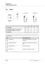
Страница 72: ...4 6FRULQJ ODGH SRVWIRUPHG FRQLFDO WRRWK mm 300 65 3 5 4 4 6FRULQJ ODGH SRVWIRUPHG IODW WRRWK mm 300 65 3 5 4 6 XWWLQJ ODGH mm 300 65 3 0 4 4 7 SH 0DFKLQDEOH 0DWHULDOV Crossed Tooth Unfaced plywood layer wood and rough chipboard Flat Trapezoidal Tooth Faced laminate melamine chipboard and MDF Trapezoidal Tooth Postformed material Conical Tooth Chipboard and faced panel scoring B C A Ø8 4 Ø8 4 Cutti...

Страница 73: ...kplace environment other sources of dust noise etc that is the number of machines and other processes in adjacent areas In any case this information allows the machine user to be able to carry out a better evaluation of risks or danger XVW PLVVLRQ The machine has passed the test for dust emission from woodworking machinery This test is carried out in accordance with the standard DIN 33893 The amou...

Страница 74: ... SSHQGL 7HFKQLFDO KDUDFWHULVWLFV BIESSE S p A Woodworking Machinery l110h046 fm 141101 ...

Страница 75: ...ied personnel who shall follow the indications given in this appendix on page C 2 The machine installation area must be aired and lit and appropriately dimensioned as well as equipped with suitable points to connect the different systems electric pneumatic etc With regard to this please see the paragraph Machine Configuration Connection Points and Overall Dimensions on page C 5 The machine connect...

Страница 76: ...ead the following lifting instructions It is recommended to unload firstly the lighter parts and then the heavier parts Before lifting any component discard all fixing equipment such as rivets ropes etc found on the carrier and which were used to fasten the machine parts for transportation LIWLQJ The illustration below shows how to carry out lifting operations for each part of the machine Use suit...

Страница 77: ...SE S p A Woodworking Machinery l111h044 fm 141101 SSHQGL 7UDQVSRUW DQG QVWDOODWLRQ DVH XLGHV 3XVKLQJ HYLFH 6XSSRUWLQJ HDP OHFWULFDO FDELQHW RQWURO TXLSPHQW Material Quantity 2 2 Already fitted yes no 1400 mm ...

Страница 78: ...se shifting is a complex operation and requires the intervention of qualified expert service engineers from BIESSE s assistance service as well as the use of a lift truck and relevant equipment On the other hand shifting of the other machine parts may be carried out using a lift truck and following the lifting methods explained above ...

Страница 79: ...V DQG 2YHUDOO LPHQVLRQV The following section contains the configuration of the machine the mains power connection points and data relevant to the overall dimensions connection point for the electric system connection point for the pneumatic system Ø 12 mm connection point for the suction system control panel Ò Ò PLQ PLQ PLQ ...

Страница 80: ...rating plate n Harmonic Distortion from the second to the fifth 10 from the sixth to the thirtieth 2 n Three phase Supply Voltage Imbalance 2 n Voltage Impulses duration less than 1 5 ms and 200 of supply voltage n Voltage Interruption duration 3 ms period 1 second n Voltage Drops value 20 of peak supply voltage period 1 second n System compliance with standards CEI 64 8 IEC 364 Machine protection...

Страница 81: ...ts of up to 5 KA If the presumed short circuit current at the supply point is higher it must be limited RQQHFWLQJ DEOH The cable connecting the machine to the supply mains shall be screened or shall pass in a metal pipe in order to reduce the electromagnetic interferences The screened cable or the metal pipe shall be earth connected The minimum section for the connecting cable shall be equal to 25...

Страница 82: ...e pipe connecting the suction system to the machine in order to disconnect the machine from the general supply system This device shall be located in a highly visible position so that the operator shall have prompt access to it The air consumption for suction is equal to 2 500 m3 h It is crucial to know this value in order to adapt the system ...

Страница 83: ...ds empty the tanks and deliver the fluids to the local authority in charge of disposal Any batteries accumulators buffer batteries for electronic cards and conditioners that may be found in the machine must also be disposed of in a suitable manner When the machine reaches the end of its technical working life it must be totally decommissioned so that it can no longer be used for the purposes for w...

Страница 84: ... SSHQGL HFRPPLVVLRQLQJ HPROLWLRQ BIESSE S p A Woodworking Machinery a112h005 fm 141101 ...

Страница 85: ... and in any case due to inappropriate use or treatment of the machine The purchaser may thus demand that any parts found to be faulty be replaced provided that such faults are not attributed to mis handling and in the case of modification provided that BIESSE S p a has issued prior written consent The purchaser shall lose any right to this guarantee if he or she does not provide BIESSE S p a with ...

Страница 86: ...odification besides modifying the supply of spare parts and accessories without any obligation on its part to inform anyone for any reason whatsoever of such changes OLHQW VHUYLFLQJ BIESSE S p A provides a service department for clients based in Pesaro ITALY which also has service workshops all over the world BIESSE Authorised Service Centres The whole structure forms a highly efficient integrated...

Страница 87: ...coring blade enabling postformed pieces scoring enabling scoring with the Ø200 mm blade enabling scoring with the Ø300 mm blade locking the blades measuring the blade belts tension pneumatic unlocking device projection optimising control regulator of the cutting blade vertical stroke replacement scoring blade scoring blade for postformed pieces start stop technical characteristics button blade sta...

Страница 88: ... suspension button cross cuts cut out valve cuts for square shaped openings cuts in sequence using fast programming cutting area cutting area laser on control cutting patterns using a cutting pattern using a series of cutting patterns danger area decommissioning demolition safety information dimensions machine overall dimensions piece draining condensate from the FR unit dust emission dust produce...

Страница 89: ...chine shipment machine s year of construction machining cross cuts cuts of variable angular direction groove execution grooving immediate complete cut enabling immediate long cut enabling immediate short cut enabling machining hold machining modes machining start button machining suspension button making an immediate cut making an immediate cut using fast programming making cuts for square shaped ...

Страница 90: ...esser vertical stroke right hand side machine scoring blade for postformed pieces side pusher stroke regulator side pusher with front roller stop for cuts of variable angular direction origins override 3 panel support piece characteristics dimensions piece loading on the right hand side PLC keyboard location pneumatic pressure supply pressure pneumatic system compressed air requirements connection...

Страница 91: ...shaped openings making start blade start control cutting area laser start control machine start control ventilating fan start control working cycle start control start up of the machine stop blade stop control of emergency of program stop control the machine types of machine stops stop for cuts of variable angular direction suction system air required for suction connection point minimum flow spee...

Страница 92: ... YL QDO WLFDO QGH BIESSE S p A Woodworking Machinery l5801l0015IX fm 141101 ...

Страница 93: ......

Страница 94: ... 66 6 S 6LWR KLXVD GL LQHVWUHWR 9LD GHOOD 0HFFDQLFD 3HVDUR WDO 7HO KWWS ZZZ ELHVVH LW KWWS ZZZ ELHVVH FRP ...

Отзывы: