


10.2
SEL-751A Relay
Instruction Manual
Date Code 20100129
Testing and Troubleshooting
Commissioning Tests
Commissioning
Tests
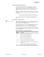
SEL performs a complete functional check and calibration of each SEL-751A
before it is shipped. This helps to ensure that you receive a relay that operates
correctly and accurately. Commissioning tests confirm that the relay is
properly connected including the control signal inputs and outputs.
The following connection tests help you enter settings into the SEL-751A and
verify that the relay is properly connected. Brief functional tests ensure that
the relay settings are correct. It is unnecessary to test every element, timer, and
function in these tests. Modify the procedure as necessary to conform to your
standard practices. Use the procedure at initial relay installation; you should
not need to repeat it unless major changes are made to the relay electrical
connections.
Required Equipment
➤
The SEL-751A, installed and connected according to your
protection design
➤
A PC with serial port, terminal emulation software, and serial
communications cable
➤
with settings appropriate to your
application and protection design
➤
The ac and dc elementary schematics and wiring diagrams for
this relay installation
➤
A continuity tester
➤
A protective relay ac test source
➢
Minimum: single-phase voltage and current with phase
angle control
➢
Preferred: three-phase voltage and current with phase
angle control
Connection Tests
Step 1. Remove control voltage and ac signals from the SEL-751A by
opening the appropriate breaker(s) or removing fuses.
Step 2. Isolate the relay contact assigned to be the
TRIP
output.
Step 3. Verify correct ac and dc connections by performing point-to-
point continuity checks on the associated circuits.
Step 4. Apply ac or dc control voltage to the relay.
After the relay is energized, the front-panel green
ENABLED
LED
should illuminate.
Step 5. Use the appropriate serial cable (SEL Cable C234A or
equivalent) to connect a PC to the relay.
Step 6. Start the PC terminal emulation software and establish
communication with the relay.
Refer to
for more information on
serial port communications.
Step 7. Set the correct relay time and date by using either the front-
panel or serial port commands.
Содержание 751A
Страница 1: ...20100129 SEL 751A Feeder Protection Relay Instruction Manual PM751A 01 NB...
Страница 6: ...This page intentionally left blank...
Страница 12: ...This page intentionally left blank...
Страница 18: ...This page intentionally left blank...
Страница 26: ...This page intentionally left blank...
Страница 92: ...This page intentionally left blank...
Страница 218: ...This page intentionally left blank...
Страница 250: ...This page intentionally left blank...
Страница 376: ...This page intentionally left blank...
Страница 392: ...This page intentionally left blank...
Страница 408: ...This page intentionally left blank...
Страница 418: ...This page intentionally left blank...
Страница 434: ...This page intentionally left blank...
Страница 462: ...This page intentionally left blank...
Страница 544: ...This page intentionally left blank...
Страница 580: ...This page intentionally left blank...
Страница 584: ...This page intentionally left blank...
Страница 632: ...This page intentionally left blank...
Страница 636: ...This page intentionally left blank...
Страница 640: ...This page intentionally left blank...


