Rostock MAX v2 Assembly Guide
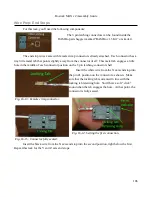
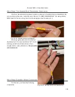
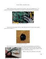
“off” position. This is shown below.
Finally, insert the switch into the mounting
hole and install & tighten the plastic nut you
threaded on to the power wires previously.
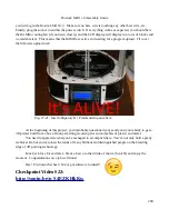
Checkpoint Video #21:
17 – Final Assembly Tasks
Attaching the Base Covers & LCD Panel
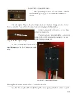
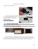
For this task, you'll need the following components:
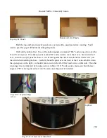
Remember back when you built the base, I had you tap the two “top” holes in each vertical
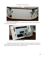
support? Now you get to use them! Install a side cover plate on the “back” sides of the Rostock MAX
v2 – between the X and Z and Y and Z axes. Use two #10-32 nylon thumbscrews on each one.
199
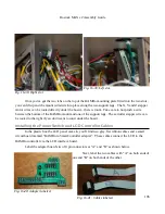
Fig. 16-48: Ready to install.
Fig. 16-49: Power switch installed.
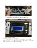
LCD Controller
Содержание Rostock MAX v2
Страница 25: ...Rostock MAX v2 Assembly Guide Melamine Parts Sheet 1 25 ...
Страница 26: ...Rostock MAX v2 Assembly Guide Melamine Parts Sheet 2 Melamine Parts Sheet 3 26 ...
Страница 27: ...Rostock MAX v2 Assembly Guide Melamine Parts Sheet 4 27 ...
Страница 171: ...Rostock MAX v2 Assembly Guide 171 Fig 14 8 Spool holder support installed ...


