Rostock MAX v2 Assembly Guide
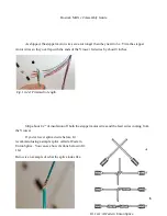
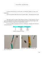
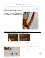
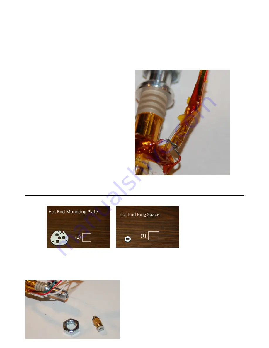
As soon as you finish soldering the white wire to the thermistor lead, cover the joint with
Kapton tape. Solder the other thermistor lead to the green wire and also cover it with Kapton. After
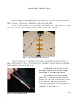
you've done that, I want you to use more Kapton and tape the two thermistor leads to the power lead
feeding the thermistor side of the hot end as shown.
The reason for this is to provide additional
strain relief to the thermistor wiring to help prevent
it from being pulled out of the hot end on accident.
Attaching the Hot End to the Hot End Mounting Plate
You'll need the following components to complete this task:
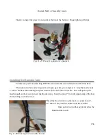
You'll also need one short wire tie and the freshly wired up hot end.
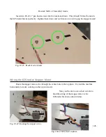
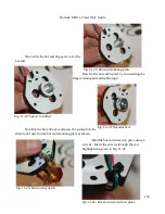
Before you can install the hot end in the hot end mounting plate, you'll need to remove both the
press-fit connector and the mounting nut as shown below.
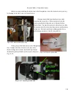
Slide the hot end into the center mounting hole on
the hot end mounting plate.
154
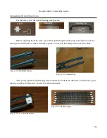
Fig. 11-20: Thermistor leads bound tight.
Fig. 11-21: Nut & press-fit removed.
Содержание Rostock MAX v2
Страница 25: ...Rostock MAX v2 Assembly Guide Melamine Parts Sheet 1 25 ...
Страница 26: ...Rostock MAX v2 Assembly Guide Melamine Parts Sheet 2 Melamine Parts Sheet 3 26 ...
Страница 27: ...Rostock MAX v2 Assembly Guide Melamine Parts Sheet 4 27 ...
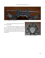
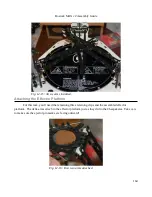
Страница 171: ...Rostock MAX v2 Assembly Guide 171 Fig 14 8 Spool holder support installed ...

