background image

WIRING DIAGRAM FOR SUPERMIG MODELS185, & 195/9.

Origin Date: 11/6/96

Issue Date: 11/6/96

Version No: 2

Modified Date: 18/09/00

TORCH PART No’s

Item      Part No            Description                 
T1        722423

Conical Nozzle

T2

722415

Contact Tip D.0.6

T3

722416

Contact Tip D.0.8

T4

722319

Nozzle Spring

T5

722326

Diffuser Insulation

T6

722823

Swan Neck Insulation

T7

722822

Swan Neck Diffuser

T8

722819

Gun Plug Housing

T9

722665

Complete Handle

T10

722007

Ring Nut

T11

722013

Liner Nut

T12

722441

Gun Plug Body

T13

722671 

Wire Guide Hose

----

722838

Complete Torch

Содержание SuperMig185

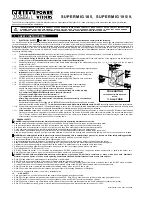
Страница 1: ...INSTRUCTIONS FOR S SU UP PE ER RM MI IG G W WE EL LD DE ER R S S U U P P E E R R M M I I G G 1 1 8 8 5 5 S S U U P P E E R R M M I I G G 1 1 9 9 5 5 9 9 SUPERMIG Models Supermig185 195 9 0051 2 180900 ...

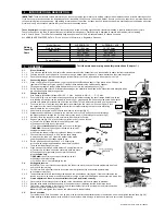
Страница 2: ...extension reel is used it should be fully unwound before connection A cable reel with an RCD fitted is recommended since any product which is plugged into the cable reel will be protected The section of the cable on the cable reel is important We recommend that at least 1 5mm2 section cable but to be absolutely sure that the capacity of the cable reel is suitable for this product and for others th...

Страница 3: ... tip back into place b Grasp gas cup in right hand push onto torch head and turn clockwise only p WARNING do not turn gas cup anti clockwise as this will damage the internal spring c Cut wire so that it is just protruding the cup 3 4 Setting wire tension IMPORTANT You must set the correct tension too little or too much tension will cause problematic wire feed and result in poor welding 3 4 1 For 0...

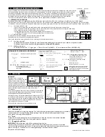
Страница 4: ...ode the wire from the contact tip at the end of the torch A gas cup fits over the contact tip to direct the gas flow towards the weld ensuring that the arc welding process is shielded from oxidising air contaminates The shielding gas also assists heating of the weld materials The torch is connected to the positive side of a DC rectifier and the negative clamp is attached to the workpiece 4 1 PREPA...

Страница 5: ...replace cup 6 5 Screen off welding site or increase gas flow Clean or grind the workpiece 4 1 1 The distance from gas cup to workpiece should be 8 10mm and torch angle 600 Chapter 5 Check hoses connections and torch assembly 6 2 Press the gas cup in correction position Replace gas cup nozzle 6 5 Check roller tension 3 4 See recommendations for wire speed 4 1 2 Use torch angle 600 chapter 5 Check r...

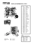
Страница 6: ...31 120 322201 Wheel 32 120 322245 Wheel 33 120 322248 Handle Rt Casing 34 120 322249 Handle Lft Casing 35 120 422257 Wire Feed Knob 36 120 422817 Support 37 120 422820 Swivel Support 38 120 432102 Gas Bottle Adaptor 39 120 452022 Spring 40 120 452057 Reel Spring 41 120 644056 Handle 42 120 644069 Back Panel 43 120 644176 Diaphragm 44 120 644606 Bracket for Bottle 45 120 648461 Front 46 120 650019 ...

Страница 7: ...T1 722423 Conical Nozzle T2 722415 Contact Tip D 0 6 T3 722416 Contact Tip D 0 8 T4 722319 Nozzle Spring T5 722326 Diffuser Insulation T6 722823 Swan Neck Insulation T7 722822 Swan Neck Diffuser T8 722819 Gun Plug Housing T9 722665 Complete Handle T10 722007 Ring Nut T11 722013 Liner Nut T12 722441 Gun Plug Body T13 722671 Wire Guide Hose 722838 Complete Torch ...

Страница 8: ...as Power Welders Signed by Mark Sweetman Models SUPERMIG185 SUPERMIG195 9 Low Voltage Directive S I 1994 3260 73 23 EEC EMC Directive S I 1992 2372 Amendments 89 336 EEC NOTE It is our policy to continually improve products and as such we reserve the right to alter data specifications and component parts without prior notice IMPORTANT No liability is accepted for incorrect use of this equipment WA...

Отзывы: