Seagull Models steen skybolt n250sb Скачать руководство пользователя страница 1

WWW.SEAGULLMODELS.COM

1

A S S E M B L Y   M A N U A L

Code : SEA237

www.seagullmodels.com

“ Graphics and specifications may change without notice “ 
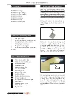
Specifications:

Wingspan---------------61 in ( 155 cm).
Wing area---------------1023 sq.in ( 66 sq.dm).
Weight-------------------9.3 lbs ( 4.2kg).
Length-------------------48.2 in (122.4cm).
Engine-------------------0.91 glow or gas
Motor--------------------1200-1700 watt electric 
   ( Power 60)
Radio--------------------6 channels with 6 servos.
Electric conversion: Optional.

Содержание steen skybolt n250sb

Страница 1: ...raphics and specifications may change without notice Specifications Wingspan 61 in 155 cm Wing area 1023 sq in 66 sq dm Weight 9 3 lbs 4 2kg Length 48 2 in 122 4cm Engine 0 91 glow or gas Motor 1200 1...

Страница 2: ...anual is designed to help you build a great flying aeroplane Please read this manual throughly before starting assembly of your STEEN SKYBOLT Use the parts listing below to indentify all parts Please...

Страница 3: ...wing panel until the T pin is snug against the wing panel This will help ensure an equal amount of hinge is on either side of the hinge line when the aileron is mounted to the aileron 3 Slide the win...

Страница 4: ...eron and wing panel 6 Using C A remover debonder and a pa per towel remove any excess C A glue that may have accumulated on the wing or in the aileron hinge area 7 Repeat this process with the other w...

Страница 5: ...ol horn Epoxy Epoxy Aileron control horn INSTALL ELEVATOR CONTROL HORN Fiberglass control horn Epoxy Elevator fiberglass control horn Epoxy INSTALL RUDDER CONTROL HORN Repeat steps to install the rudd...

Страница 6: ...ts and brass collets onto the throttle servo Test fit the servo into the aileron servo mount 2 Secure the servos with the screws pro vided with your radio system Rudder servo Elevator servo Throttle s...

Страница 7: ...ing a modeling knife cut one length of silicon fuel line Connect one end of the line to the weighted fuel pick up and the other end to the nylon pick up tube A B Vent tube Fuel pick up tube Fuel fill...

Страница 8: ...vent and which is the fuel pickup when you attach fuel tubing to the tubes in the stopper Once the tank is installed inside the fuselage it may be difficult to determine which is which 7 Slide the fu...

Страница 9: ...mm 2 Use a pin drill and 4mm drill bit to drill a small indentation in the mount for the engine mounting screw 3 Use a drill to drill the four holes in the engine mount rails 4mm 4mm 4 On the fire wal...

Страница 10: ...er the pushrod wire Center the throttle stick and trim and install the servo horn perpendicular to the servo center line 9 Movethethrottlesticktotheclosed po sition and move the carburetor to closed U...

Страница 11: ...o the end of the needle valve Secure the wire in place by tightening the set screw in the side of the needle valve 1 Carefully align the cowling on the air plane The front of the cowl should be posi t...

Страница 12: ...o secure the landing gear to the fu selage using bolts M4x20mm and wash ers Make sure to use the threadlock on the bolts so they don t vibrate loose INSTALLING THE MAIN LANDING GEAR TO FUSELAGE M4x20m...

Страница 13: ...g Use a washer and lock nut to tighten the axle to the landing gear Make sure to use threadlock on the nut so it won t vibrate loose in flight as shown 7 Tighten the setcrews using a hex wrench to sec...

Страница 14: ...itable with the cross lines drawn on the electric motor box and fire wall Using M4x20mm to secure the mo tor box to the firewall Please see pictures below Motor approx 1200 1700 watt 390 600kv 50mm di...

Страница 15: ...lts to se cure the motor Please see picture shown 130 mm Epoxy M3x12mm Speed control Balsa stick Epoxy 6 Attach the speed control to the side of the motor box using two sided tape and tie wraps Connec...

Страница 16: ...SERVOS Servos Small weight Thread Because the size of servos differ you may need to adjust the size of the precut opening in the mount The notch in the sides of the mount allow the servo lead to pass...

Страница 17: ...re the connec tion so they cannot become unplugged 6 Secure the servo to the aileron hatch using Phillips screwdriver and the screws provided with the servo 7 Apply 1 2 drops of thin C A to each of th...

Страница 18: ...YBOLT Instruction Manual 18 9 Set the aileron hatch in place and use a Phillips screw driver to install it with four wood screws 2x10mm INSTALLING THE AILERON SERVO Repeat the procedure for the ailero...

Страница 19: ...o arm Fuel tubing Hex Nut Nylon Snap keeper INSTALLING THE HORIZONTAL STABILIZER 1 Using a ruler and a pen locate the cen terline of the horizontal stabilizer at the trailing edge and place a mark Use...

Страница 20: ...covering itself Cut ting into the balsa structure may weaken it 6 Using a modeling knife carefully re move the covering that overlaps the sta bilizer mounting platform sides in the fuselage Remove th...

Страница 21: ...ertical stabilizer back in place Using a triangle check to ensure that the vertical stabilizer is aligned 90 to the horizontal stabilizer 2 While holding the vertical stabilizer firmly in place use a...

Страница 22: ...king tape and remove any excess epoxy using a paper towel and rubbing alcohol Allow the epoxy to fully cure before proceeding After the epoxy is dry glue the lower rudder hinge with thin CA Hex nut Fu...

Страница 23: ...Elevator control horn Rudder control horn Rudder pushrod RUDDERPUSHRODHORN INSTALLATION 1 Locate items necessary to install rud der pushrod Repeat steps to install the remaining el evator pushrod M2 l...

Страница 24: ...1 Locate items necessary to install pilot seats 2 A scale pilot is included with this ARF The Seagull Pilot included fitting well to the cockpit or you can order others scale pilot figures made by Sea...

Страница 25: ...e with epoxy glue or special canopy glue 2 Use a hobby knife with blade to re move the covering on the top of the fuse lage so the cabane struts can be inserted into the fuselage We recommend using a...

Страница 26: ...d M3 washers Leave the hardware loose so the struts can be positionedwhileinstallingtheupperwing center rib Maker sure to use threadlock on the screws so they won t vibrate loose 4 Place the upper cen...

Страница 27: ...ULLMODELS COM 27 Receiver Battery ATTACHMENT WING FUSELAGE Cut Epoxy Insert two wing panels as pictures below Attach the aluminium tube into fuselage Wing tube Insert cover hatch on fuselage as pictur...

Страница 28: ...STEEN SKYBOLT Instruction Manual 28 Wing bolt Epoxy INSTALLATION WING STRUTS 1 Locate the items for this section of the manual 4x10mm...

Страница 29: ...tween the top and bottom ailerons With the radio system on and the bottom aileron con tered adjust the length to center the top aileron Once centered slide the silicone tubing over the forks of the cl...

Страница 30: ...ion we rec ommend With the wing attached to the fuselage all parts of the model installed ready to fly and empty fuel tanks hold the model at the marked balance point with the sta bilizer level Lift t...

Страница 31: ...WWW SEAGULLMODELS COM 31...

Страница 32: ...the airplane look at the aileron on the right wing half Move the aileron stick to the right The right aileron should move up and the other aileron should move down If it does not flip the servo rever...

Отзывы: