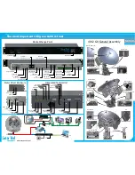
Model 4012 GX
Quick Start Guide
The most important thing we build is trust
www.cobham.com/seatel
GPS Antenna
ICU
Elevation Stowage
Ku-Band RF Cage
Air Cylinder
EL Drive Motor
AZ Drive Motor
Wire Rope Isolators
Azimuth Drive Chain
Motor Driver Enclosure
CL Drive Motor
Ku Band Feed Tube
Proximity Sensor
Azimuth Stowage
AC Power Ring
Rotary Joint
136875 Revision B
Ship’s AC Mains
Sat Modem
(Type ‘F’ Rx L-Band)
Antenna
(SMA EoC + Rx L-Band)
EoC Status LED
Fiber Interface
(SFP Gigabit Ethernet)
N/C
(Future Development)
Computer
(DE9 Serial Antenna M&C)
Computer
(RJ45 Serial M&C)
Gyro Compass
(SBS/Synchro Interface)
Gyro Compass
(NMEA 0183 Interface)
RS-232 Serial
Passthrough
Ancillary
Equipment
Gyro Compass
(NMEA 2000 Interface/
Future Developement)
Sat Modem
(RJ45 Serial M&C)
OBM Appliance
(RJ45 Serial M&C)
Computer
(Mini USB Antenna M&C)
Computer
(4 Port 10/100 Ethernet Switch 10.1.1.100)
Status LED’s
Power Switch
Media Xchange Point
Home Flag
To AZ Motor
To ICU
Status LED’S
Computer
To EL Motor
To CL Motor
Motor Driver Enclosure
Integrated Control Unit
To Xpol LNB
To CoPol LNB
To Rotary Joint
N/C
Computer
To Power Ring
EoC Status LED
Computer
ICU Status LED
To GPS
To MDE
To RF Cage
BUC
(M&C)
To BUC
(DC In)
Computer
Computer
4012 GX General Assembly
*Graphic Representation only, actual hardware may vary
Sat Modem
To AC
Mains
PC
FAX
VoIP
Router
Firewall
PC
To AC
Mains
Optional Out of Band Management


