Page 5 of 11
123-652 Rev -
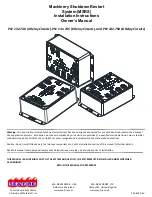
Compatible Display Panels: “Fire Suppression System Monitor and Engine Shutdown Control”
Part Number
Display Panel indicators and shape
131-460
Power and Discharge Indication, Rectangle
131-461
Power and Discharge Indication, Round
131-462
Power, Discharge, and High Temp Indication, Rectangle
131-463
Power, Discharge, and High Temp Indication, Round
131-464
Power, Discharge, and Aux Zone Indication, Rectangle
131-465
Power, Discharge, and Aux Zone Indication, Round
131-466
Power, Discharge, and Low-Pressure Indication, Rectangle
131-467
Power, Discharge, and Low-Pressure Indication, Round
3.3.1.5
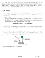
Multiple Cylinder Supervisory Switch Connection to the MSRS PS1
When connecting more than one pre-engineered cylinder supervisory pressure switch to the MSRS Unit,
connect all the supervisory pressure switches in series. Connect the leading switch wire to Terminal
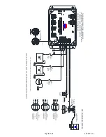
marked “1” and the trailing wire of the last pressure switch to Terminal marked “2” (See Figure 2).
When connecting more than one Engineered System cylinder supervisory switch to the MSRS unit, connect
all the cylinder supervisory switches in series. Connect the leading switch wire to Terminal marked “3”
and the trailing wire of the last pressure switch to Terminal marked “4” (See Figure 2).
When connecting more than one Engineered System discharge pressure switch, reference the engineered
fire suppression manual and electrical circuit diagram provided as part of the system.
3.3.1.6
Engine or Machinery connection
Refer to the Original Equipment Manufacturers (OEM) Engine or the machinery Installation manual for the
correct method of connection to relays of the MSRS unit. Equipment manufacturers have a variety of
methods to control their equipment.
The following section provides the basic operation of the relays in the MSRS unit.
4
Relay Operation:
This section provides the basic operation of the relays in the ESRS unit.
4.1.
Relay Contact Specification
Table 1 Relay Contact Specification
Item
Value
Contact
SPDT (1 Form C)
Contact Current
10A NC / 20A NO
Contact Voltage VAC (Maximum allowable) 277VAC
N/C – Normally Closed Contact
N/O – Normally Open Contact
COM – Common Terminal
4.2.
Relay De-Energized State
When the MSRS is operational and in the standby mode, all the relays should be in the de-energized state.
The N/C and the COM terminals are connected.
The N/O terminal is open.
Содержание 131-740
Страница 11: ...Page 11 of 11 123 652 Rev ...


