


Section 03 ENGINE SYSTEM
Subsection 04 (EXHAUST SYSTEM)
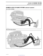
RESONATOR
Removal
RXP Models
Remove supercharger inlet hose.
Disconnect speed sensor connector.
Remove VTS. Refer to VARIABLE TRIM SYSTEM.
All Models
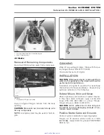
Disconnect inlet hose
no. 8
.
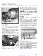
Remove dart
no. 9
retaining resonator
no. 11
.
Disconnect outlet hose
no. 10
from resonator.
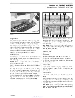
F19D03A
3
1
2
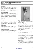
1. Inlet hose
2. Retaining screw
3. Outlet hose
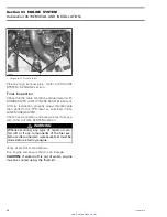
Carefully pull out the resonator
no. 11
.
F19D04A
Inspection
Inspect parts condition paying attention for defor-
mation, cracks or other damage. Check hoses.
Replace any defective part.
Installation
Installation is the reverse of the removal proce-
dures.
For resonator installation, remove outlet hose
no. 10
from exhaust outlet
no. 12
.
Install outlet hose on resonator.
Install resonator in position while inserting outlet
hose
no. 10
on exhaust outlet.
After installation, ensure there is no coolant or ex-
haust gas leak when the engine is running. Test
run the engine while supplying water to the flush-
ing connector.
CAUTION:
Never run engine without supplying
water to the exhaust cooling system when wa-
tercraft is out of water.
EXHAUST OUTLET
Removal
Remove resonator retaining dart
no. 9
. Move res-
onator forward and disconnect outlet hose
no. 10
from exhaust outlet
no. 12
.
Remove the jet pump as an assembly from pump
support. Refer to PROPULSION SYSTEM.
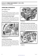
From outside of hull, unscrew nut
no. 13
with the
exhaust outlet tool (P/N 295 000 132).
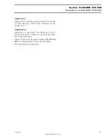
F19D05A
1
2
TYPICAL
1. Exhaust outlet nut
2. Exhaust outlet tool
From inside the bilge, remove exhaust outlet.
56
smr2005-009
www.SeaDooManuals.net


