


Section 04 ENGINE MANAGEMENT (1503 4-TEC)
Subsection 03 (COMPONENT INSPECTION, REPLACEMENT AND ADJUSTMENT)
NOTE:
Take into account that a CPS fault can be
triggered by a bent or missing trigger wheel tooth.
First check fault codes then CPS as per follow-
ing procedure; if it tests good, verify trigger wheel
teeth condition. Refer to PTO HOUSING/ MAG-
NETO in the
1503 4-TEC ENGINE SHOP MANU-
AL
.
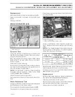
Disconnect CPS wiring harness connector. Probe
terminals coming from CPS while cranking engine.
Voltage should be within 1 - 2 Vac. Otherwise,
inspect wiring and replace CPS if wiring is good.
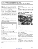
Resistance Test
Disconnect the CPS connector from the wiring
harness and check the resistance of the sensor
itself.
The resistance should be between 190
and
290
.
Otherwise, replace the CPS.
If resistance tests good, reconnect the CPS and
disconnect the ECM connector A on the ECM.
Using a multimeter, recheck resistance value be-
tween terminals 5 and 19.
If resistance value is correct, try a new ECM. Refer
to ECM AND MPEM in this section.
If resistance value is incorrect, repair the connec-
tors or replace the wiring harness between ECM
connector and the CPS.
Replacement
Disconnect connectors and remove the PTO cov-
er. Refer to PTO HOUSING/MAGNETO in the
1503 4-TEC ENGINE SHOP MANUAL
.
Trigger Wheel Inspection
Refer to PTO HOUSING/MAGNETO in the
1503
4-TEC ENGINE SHOP MANUAL
.
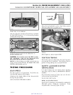
CAMSHAFT POSITION SENSOR
(CAPS)
1
R1503motr178A
1. CAPS
Voltage Test (harness)
Disconnect the connector from the wiring har-
ness.
To see the connector pin-out, temporarily remove
the connector shield joining the harness, to ex-
pose the terminal numbers.
Remove and reinstall safety lanyard to activate the
system.
Probe terminal 3 of CAPS connector (wiring har-
ness side) and battery ground.
– If 12 V is read, check continuity of circuits A-20
and A-34. If they test good, perform the CAPS
voltage test as explained below. If CAPS tests
good, try a new ECM.
– If 12 V is not read, check continuity of circuit
2-19 from MPEM to the CAPS. If it tests good,
try a new MPEM. Otherwise, repair wiring har-
ness.
Remove the CAPS from the cylinder head.
Set up the following electric circuit to perform the
voltage test.
smr2005-013
123
www.SeaDooManuals.net


