


Section 04 ENGINE MANAGEMENT (1503 4-TEC)
Subsection 03 (COMPONENT INSPECTION, REPLACEMENT AND ADJUSTMENT)
A32CCPA
PROBE ONLY TOP OF TERMINAL
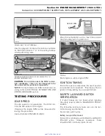
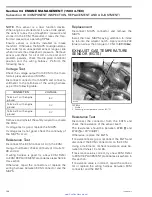
Use this diagram to locate the terminal numbers
on the ECM connector “A” of the wiring harness
when performing tests.
R1503motr176A
1
13
28
41
29
14
TERMINAL IDENTIFICATION OF ECM CONNECTOR ”A”
(WIRING HARNESS SIDE)
CAUTION:
Do not disconnect the ECM connec-
tors needlessly. They are not designed to be
disconnected/reconnected repeatedly.
NOTE:
For more details on ECM connectors ser-
vicing, refer to ELECTRICAL CONNECTORS AND
WIRING DIAGRAMS section.
TESTING PROCEDURES
IDLE SPEED
The idle speed is not adjustable. The ECM con-
trols the idle speed of the engine.
If desired, the engine RPM can be measured fol-
lowing this procedure:
Use tachometer (P/N 529 014 500).
529 014 500
Wrap the tachometer's wire a few times around
the protruding part of ignition coil.
A32CCIA
TYPICAL
Start engine to verify engine RPM.
IGNITION TIMING
The ECM is able to determine the exact position
of camshaft and crankshaft. That means that no
ignition timing setting has to be performed.
SAFETY LANYARD SWITCH
VERIFICATION
If 2 short beeps are not heard when installing
the safety lanyard, refer to DIAGNOSTIC PROCE-
DURES.
The following continuity tests can also be per-
formed using an ohmmeter.
Disconnect switch wires.
Safety Lanyard Removed
Connect test probes to switch BLACK and BLACK/
YELLOW wires.
Measure resistance,
there
should be NO continuity (open circuit).
smr2005-013
111
www.SeaDooManuals.net


