


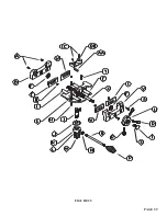


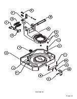

8.4 GEAR REPLACEMENT
SEE FIGURE 23 ON THE FOLLOWING PAGE.
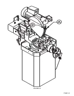
1. Remove the drain plug (A) from the head casting and allow the fluid to drain.
2. Remove the motor from the head.
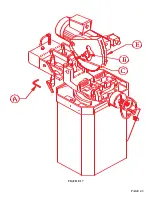
3. Remove the four bolts (E) from the bearing retainer (F).
4. Remove the worm shaft assembly (J). The worm shaft has a 10mm threaded hole in the end of it for
a slide hammer. This is the preferred method of removing the shaft. If you do not have a slide
hammer, the shaft can be removed by driving it out with a brass drift pin.
5. Inspect the worm shaft, drive gear and bearings for wear.
6. After the worm shaft has been removed, remove the three bolts (M) from the bearing housing (O).
7. Remove the spindle shaft (N) with a slide hammer. This shaft can also be removed by driving it out of
the head casting with a brass drift pin.
8. Remove the snap ring (R).
9. The brass worm gear (Q) can now be pressed off of the shaft.
10. Check the condition of the bearings and the seals before re-assembling the head.
11. Check the condition of the key (P) and the key-way in the gear and the spindle shaft before pressing
the new gear onto the shaft.
PAGE 54
Содержание CPO 350
Страница 1: ...CPO 350 VARIABLE SPEED COLD SAW PRINTED SEPTEMBER 2014...
Страница 7: ...PAGE 7 FIGURE 1...
Страница 8: ...4 2 MACHINE MOVING PROCEDURES SEE FIGURE 2 BELOW PAGE 8 FIGURE 2...
Страница 11: ...PAGE 11 350 VS POWER DOWN 230 VOLT SEE PAGE 47 FOR POWER DOWN WIRING FIGURE 3 1...
Страница 12: ...PAGE 12 350 VS MANUAL PK 230 VOLT FIGURE 3 2...
Страница 13: ...PAGE 13 350 VS POWER DOWN 460 VOLT SEE PAGE 47 FOR POWER DOWN WIRING FIGURE 3 3...
Страница 14: ...PAGE 14 350 VS MANUAL PK 460 VOLT FIGURE 3 4...
Страница 17: ...PAGE 17 FIGURE 4...
Страница 19: ...PAGE 19 FIGURE 5...
Страница 27: ...PAGE 27 FIGURE 8 FIGURE 9...
Страница 29: ...PAGE 29 FIGURE 10...
Страница 33: ...PAGE 33 FIGURE 12...
Страница 35: ...PAGE 35 FIGURE 13...
Страница 37: ...PAGE 37 FIGURE 14...
Страница 39: ...PAGE 39 FIGURE 15...
Страница 41: ...PAGE 41 FIGURE 16...
Страница 43: ...PAGE 43 FIGURE 17...
Страница 45: ...7 2F POWER DOWN FEED WIRING DIAGRAM Ser s 6425 Up PAGE 45 FIGURE 19...
Страница 46: ...7 2G PNEUMATIC SCHEMATIC POWER DOWN MACHINES PAGE 46 FIGURE 20...
Страница 47: ...THIS PAGE LEFT BLANK INTENTIONALLY PAGE 47...
Страница 49: ...PAGE 49 FIGURE 21...
Страница 51: ...PAGE 51 FIGURE 22...
Страница 55: ...PAGE 55 FIGURE 23...
Страница 59: ...PAGE 59 FIGURE 25...
Страница 61: ...PAGE 61 FIGURE 26...
Страница 63: ...PAGE 63 FIGURE 27...
Страница 65: ...PAGE 65 FIGURE 28...
Страница 67: ...PAGE 67 FIGURE 29...
Страница 69: ...PAGE 69 FIGURE 30...
Страница 71: ...PAGE 71 FIGURE 31...
Страница 73: ...PAGE 73 FIGURE 32...
Страница 75: ...PAGE 75 FIGURE 33...
Страница 77: ...PAGE 77 FIGURE 33...
Страница 79: ...PAGE 79 FIGURE 34...
Страница 81: ...PAGE 81 FIGURE 35...
Страница 83: ...PAGE 83 FIGURE 36...
Страница 85: ...PAGE 85 FIGURE 37...
Страница 87: ...PAGE 87 FIGURE 38...
Страница 89: ...PAGE 89 FIGURE 39...
Страница 91: ...PAGE 91 FIGURE 40...
Страница 93: ...PAGE 93 FIGURE 41...