


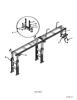


7.4 DISCHARGE TRACKS WITH SCALES
Roller discharge tracks equipped with either a right or left hand quick-loc are available in two lengths:
60" and 120" (122 & 303 CM).
The discharge tracks mount to the machine in place of the 30 inch (76 CM) stop that was provided with
the machine. The discharge tracks allow fast set-up and accuracy for various lengths of cuts.
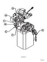
SEE FIGURE 22 ON THE FOLLOWING PAGE.
1. Bolt the support bracket (A) to the side of the base casting with the 10 x 30mm head bolts and
lock washers provided.
2. Bolt the legs (B) to the rail assembly (C) with the remaining 10 x 30mm hex head bolts.
3. Place the two remaining 10 x 80mm hex bolts through the end of the rail assembly and lock them in
place with the hex nuts.
4. Thread another nut on each bolt and attach the track to the support bracket with the remaining two
10mm hex nuts.
5. Space the rollers along the rail at an even spacing.
6. Adjust the discharge track so that the rollers are at the same level as the bed of the material vise on
the saw. The track is adjusted by loosening the bolts in the legs and the two bolts that attach the rail to
the support bracket.
7. After a discharge track is mounted, the scale should be calibrated. To do this, draw the saw head
down and set the quick-loc extension (6) ten inches from the blade. Install the scale so that the ten
inch mark lines up to the quick-loc pointer. When the quick-loc extension (5) is used, you have to
add ten inches to the length of the part that you want to cut. If the stop requires fine adjustments,
remove the quick-loc handle from the track and turn it over. There is a fine adjustment on the
bottom side of the quick-loc handle.
PAGE 50
Содержание CPO 350
Страница 1: ...CPO 350 VARIABLE SPEED COLD SAW PRINTED SEPTEMBER 2014...
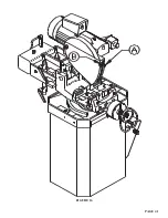
Страница 7: ...PAGE 7 FIGURE 1...
Страница 8: ...4 2 MACHINE MOVING PROCEDURES SEE FIGURE 2 BELOW PAGE 8 FIGURE 2...
Страница 11: ...PAGE 11 350 VS POWER DOWN 230 VOLT SEE PAGE 47 FOR POWER DOWN WIRING FIGURE 3 1...
Страница 12: ...PAGE 12 350 VS MANUAL PK 230 VOLT FIGURE 3 2...
Страница 13: ...PAGE 13 350 VS POWER DOWN 460 VOLT SEE PAGE 47 FOR POWER DOWN WIRING FIGURE 3 3...
Страница 14: ...PAGE 14 350 VS MANUAL PK 460 VOLT FIGURE 3 4...
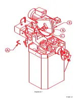
Страница 17: ...PAGE 17 FIGURE 4...
Страница 19: ...PAGE 19 FIGURE 5...
Страница 27: ...PAGE 27 FIGURE 8 FIGURE 9...
Страница 29: ...PAGE 29 FIGURE 10...
Страница 33: ...PAGE 33 FIGURE 12...
Страница 35: ...PAGE 35 FIGURE 13...
Страница 37: ...PAGE 37 FIGURE 14...
Страница 39: ...PAGE 39 FIGURE 15...
Страница 41: ...PAGE 41 FIGURE 16...
Страница 43: ...PAGE 43 FIGURE 17...
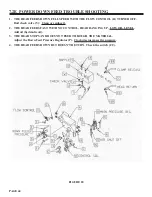
Страница 45: ...7 2F POWER DOWN FEED WIRING DIAGRAM Ser s 6425 Up PAGE 45 FIGURE 19...
Страница 46: ...7 2G PNEUMATIC SCHEMATIC POWER DOWN MACHINES PAGE 46 FIGURE 20...
Страница 47: ...THIS PAGE LEFT BLANK INTENTIONALLY PAGE 47...
Страница 49: ...PAGE 49 FIGURE 21...
Страница 51: ...PAGE 51 FIGURE 22...
Страница 55: ...PAGE 55 FIGURE 23...
Страница 59: ...PAGE 59 FIGURE 25...
Страница 61: ...PAGE 61 FIGURE 26...
Страница 63: ...PAGE 63 FIGURE 27...
Страница 65: ...PAGE 65 FIGURE 28...
Страница 67: ...PAGE 67 FIGURE 29...
Страница 69: ...PAGE 69 FIGURE 30...
Страница 71: ...PAGE 71 FIGURE 31...
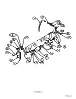
Страница 73: ...PAGE 73 FIGURE 32...
Страница 75: ...PAGE 75 FIGURE 33...
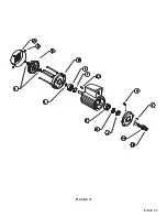
Страница 77: ...PAGE 77 FIGURE 33...
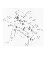
Страница 79: ...PAGE 79 FIGURE 34...
Страница 81: ...PAGE 81 FIGURE 35...
Страница 83: ...PAGE 83 FIGURE 36...
Страница 85: ...PAGE 85 FIGURE 37...
Страница 87: ...PAGE 87 FIGURE 38...
Страница 89: ...PAGE 89 FIGURE 39...
Страница 91: ...PAGE 91 FIGURE 40...
Страница 93: ...PAGE 93 FIGURE 41...