


5.3 SCHEDULED MAINTENANCE
A program of scheduled maintenance should be set up and documented according to your application and
the frequency you use this machine. The following is a list of some important things that should be
included in a scheduled maintenance program.
1. EVERY 250 HOURS OR 3 MONTHS:
Drain the coolant reservoir and flush it out. Refill the coolant reservoir with new coolant.
This will extend the life of the coolant pump considerably.
2. EVERY 500 HOURS OR 6 MONTHS:
Drain the gear lube from the saw head and flush with a petroleum product.
Refill the saw head with Mobil 600W Super Cylinder Oil or equivalent.
Gear lube is added to the saw by removing the draw handle or breather fitting from the top of the saw
head.
Check the condition of the pivot pins on the head and on the guard.
Check the complete saw for loose connections in the electrical and air systems.
If your saw is equipped with the power vise or power down feed options, SEE SECTIONS 7.1 THRU 7.2,
for additional information.
Since every application is different, each user must design and implement a scheduled maintenance
program that fits his applications.
PAGE 21
Содержание CPO 350
Страница 1: ...CPO 350 VARIABLE SPEED COLD SAW PRINTED SEPTEMBER 2014...
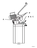
Страница 7: ...PAGE 7 FIGURE 1...
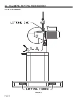
Страница 8: ...4 2 MACHINE MOVING PROCEDURES SEE FIGURE 2 BELOW PAGE 8 FIGURE 2...
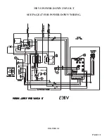
Страница 11: ...PAGE 11 350 VS POWER DOWN 230 VOLT SEE PAGE 47 FOR POWER DOWN WIRING FIGURE 3 1...
Страница 12: ...PAGE 12 350 VS MANUAL PK 230 VOLT FIGURE 3 2...
Страница 13: ...PAGE 13 350 VS POWER DOWN 460 VOLT SEE PAGE 47 FOR POWER DOWN WIRING FIGURE 3 3...
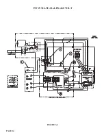
Страница 14: ...PAGE 14 350 VS MANUAL PK 460 VOLT FIGURE 3 4...
Страница 17: ...PAGE 17 FIGURE 4...
Страница 19: ...PAGE 19 FIGURE 5...
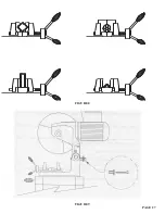
Страница 27: ...PAGE 27 FIGURE 8 FIGURE 9...
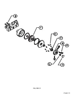
Страница 29: ...PAGE 29 FIGURE 10...
Страница 33: ...PAGE 33 FIGURE 12...
Страница 35: ...PAGE 35 FIGURE 13...
Страница 37: ...PAGE 37 FIGURE 14...
Страница 39: ...PAGE 39 FIGURE 15...
Страница 41: ...PAGE 41 FIGURE 16...
Страница 43: ...PAGE 43 FIGURE 17...
Страница 45: ...7 2F POWER DOWN FEED WIRING DIAGRAM Ser s 6425 Up PAGE 45 FIGURE 19...
Страница 46: ...7 2G PNEUMATIC SCHEMATIC POWER DOWN MACHINES PAGE 46 FIGURE 20...
Страница 47: ...THIS PAGE LEFT BLANK INTENTIONALLY PAGE 47...
Страница 49: ...PAGE 49 FIGURE 21...
Страница 51: ...PAGE 51 FIGURE 22...
Страница 55: ...PAGE 55 FIGURE 23...
Страница 59: ...PAGE 59 FIGURE 25...
Страница 61: ...PAGE 61 FIGURE 26...
Страница 63: ...PAGE 63 FIGURE 27...
Страница 65: ...PAGE 65 FIGURE 28...
Страница 67: ...PAGE 67 FIGURE 29...
Страница 69: ...PAGE 69 FIGURE 30...
Страница 71: ...PAGE 71 FIGURE 31...
Страница 73: ...PAGE 73 FIGURE 32...
Страница 75: ...PAGE 75 FIGURE 33...
Страница 77: ...PAGE 77 FIGURE 33...
Страница 79: ...PAGE 79 FIGURE 34...
Страница 81: ...PAGE 81 FIGURE 35...
Страница 83: ...PAGE 83 FIGURE 36...
Страница 85: ...PAGE 85 FIGURE 37...
Страница 87: ...PAGE 87 FIGURE 38...
Страница 89: ...PAGE 89 FIGURE 39...
Страница 91: ...PAGE 91 FIGURE 40...
Страница 93: ...PAGE 93 FIGURE 41...