


4.6 GUARD ADJUSTMENT-MANUAL MACHINES
SEE FIGURE 4 ON THE FOLLOWING PAGE.
FOR GUARD ADJUSTMENT PROCEDURES ON SAWS EQUIPPED WITH THE POWER DOWN
FEED OPTION, REFER TO SECTION 7.2C.
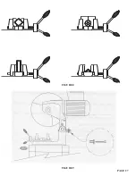
The proper adjustment of the blade guard on this machine is crucial to the operation of the machine and
the safety of the operator. If the guard will not maintain proper adjustment, check the guard mounting
bolts and rivet joints in the guard and linkage for wear. Replace worn parts promptly.
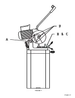
USE THE FOLLOWING STEPS TO ADJUST THE BLADE GUARD:
1. Turn the power off and disconnect from the power source.
2. With the head in the UP position, loosen the mounting bolts (A) on the linkage mount (B).
3. Manually hold the guard open approximately 1/8 of an inch (3 mm) at point (C).
4. Adjust the linkage mount (B) down until there is tension on the linkage bar. Re-tighten the linkage
mount bolts (A).
5. Manually cycle the head up and down several times, making sure that the guard operates properly.
PAGE 16
Содержание CPO 350
Страница 1: ...CPO 350 VARIABLE SPEED COLD SAW PRINTED SEPTEMBER 2014...
Страница 7: ...PAGE 7 FIGURE 1...
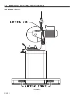
Страница 8: ...4 2 MACHINE MOVING PROCEDURES SEE FIGURE 2 BELOW PAGE 8 FIGURE 2...
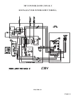
Страница 11: ...PAGE 11 350 VS POWER DOWN 230 VOLT SEE PAGE 47 FOR POWER DOWN WIRING FIGURE 3 1...
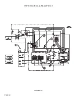
Страница 12: ...PAGE 12 350 VS MANUAL PK 230 VOLT FIGURE 3 2...
Страница 13: ...PAGE 13 350 VS POWER DOWN 460 VOLT SEE PAGE 47 FOR POWER DOWN WIRING FIGURE 3 3...
Страница 14: ...PAGE 14 350 VS MANUAL PK 460 VOLT FIGURE 3 4...
Страница 17: ...PAGE 17 FIGURE 4...
Страница 19: ...PAGE 19 FIGURE 5...
Страница 27: ...PAGE 27 FIGURE 8 FIGURE 9...
Страница 29: ...PAGE 29 FIGURE 10...
Страница 33: ...PAGE 33 FIGURE 12...
Страница 35: ...PAGE 35 FIGURE 13...
Страница 37: ...PAGE 37 FIGURE 14...
Страница 39: ...PAGE 39 FIGURE 15...
Страница 41: ...PAGE 41 FIGURE 16...
Страница 43: ...PAGE 43 FIGURE 17...
Страница 45: ...7 2F POWER DOWN FEED WIRING DIAGRAM Ser s 6425 Up PAGE 45 FIGURE 19...
Страница 46: ...7 2G PNEUMATIC SCHEMATIC POWER DOWN MACHINES PAGE 46 FIGURE 20...
Страница 47: ...THIS PAGE LEFT BLANK INTENTIONALLY PAGE 47...
Страница 49: ...PAGE 49 FIGURE 21...
Страница 51: ...PAGE 51 FIGURE 22...
Страница 55: ...PAGE 55 FIGURE 23...
Страница 59: ...PAGE 59 FIGURE 25...
Страница 61: ...PAGE 61 FIGURE 26...
Страница 63: ...PAGE 63 FIGURE 27...
Страница 65: ...PAGE 65 FIGURE 28...
Страница 67: ...PAGE 67 FIGURE 29...
Страница 69: ...PAGE 69 FIGURE 30...
Страница 71: ...PAGE 71 FIGURE 31...
Страница 73: ...PAGE 73 FIGURE 32...
Страница 75: ...PAGE 75 FIGURE 33...
Страница 77: ...PAGE 77 FIGURE 33...
Страница 79: ...PAGE 79 FIGURE 34...
Страница 81: ...PAGE 81 FIGURE 35...
Страница 83: ...PAGE 83 FIGURE 36...
Страница 85: ...PAGE 85 FIGURE 37...
Страница 87: ...PAGE 87 FIGURE 38...
Страница 89: ...PAGE 89 FIGURE 39...
Страница 91: ...PAGE 91 FIGURE 40...
Страница 93: ...PAGE 93 FIGURE 41...