Scotchman CPO 350 Скачать руководство пользователя страница 12

PAGE 12

350 VS MANUAL & PK 230 VOLT

FIGURE 3-2

Содержание CPO 350

Страница 1: ...CPO 350 VARIABLE SPEED COLD SAW PRINTED SEPTEMBER 2014...

Страница 2: ...tting Speed 25 6 4 Material Clamping 26 6 5 Miter Locking Device 28 7 0 OPTIONAL EQUIPMENT 30 7 1 Power Vise 30 7 1A Power Vise Set up Maintenance 30 7 1B Replacing the Spindle in the Air Vise 32 7 1C...

Страница 3: ...st Base Pedestal 68 9 8 Material Stop 30 Inch 76 CM 70 9 9 Variable Speed Motor Control 72 9 10 Cast Saw Blade Cabinet 74 10 0 OPTIONAL EQUIPMENT PARTS LISTS 76 10 1 Power Vise Assembly 76 10 2 Power...

Страница 4: ...esides the mill quality cut cold saws have the ability to generate faster cutoff times than band saws There are no sparks and excessive noises that are associated with abrasive cutoff saws Cold saws a...

Страница 5: ...seller which shall be the buyer s sole and exclusive remedy for defective goods Hydraulic and electric components are subject to their respective manufacturer s warranties This warranty does not appl...

Страница 6: ...FEED OPTION READ ALL SECTIONS CONCERNING THESE OPTIONS BEFORE OPERATING THE SAW 4 1 PHYSICAL DIMENSIONS SEE FIGURE 1 ON THE FOLLOWING PAGE DIMENSIONS INCHES CM A HEIGHT 67 5 171 4 B FLOOR TO VISE 37...

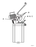
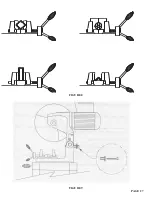
Страница 7: ...PAGE 7 FIGURE 1...

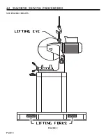
Страница 8: ...4 2 MACHINE MOVING PROCEDURES SEE FIGURE 2 BELOW PAGE 8 FIGURE 2...

Страница 9: ...MACHINES OTHER THAN THIS SAW MAKE SURE THAT THE DRAW HANDLE HAS A JAM NUT ON THE THREADS BEFORE INSTALLING IT ON THE SAW IF THE HANDLE IS INSTALLED WITHOUT THE JAM NUT IT MAY CONTACT THE GEARS INSIDE...

Страница 10: ...same voltage as your plant voltage you will have to replace the variable speed drive change the primary leads on the transformer and rewire the motor To insure satisfactory performance the supply vol...

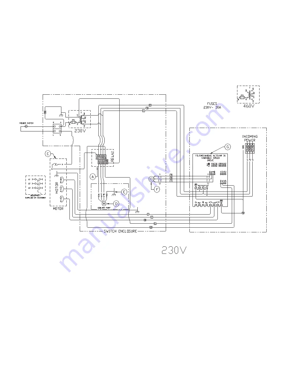
Страница 11: ...PAGE 11 350 VS POWER DOWN 230 VOLT SEE PAGE 47 FOR POWER DOWN WIRING FIGURE 3 1...

Страница 12: ...PAGE 12 350 VS MANUAL PK 230 VOLT FIGURE 3 2...

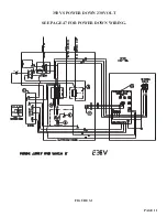
Страница 13: ...PAGE 13 350 VS POWER DOWN 460 VOLT SEE PAGE 47 FOR POWER DOWN WIRING FIGURE 3 3...

Страница 14: ...PAGE 14 350 VS MANUAL PK 460 VOLT FIGURE 3 4...

Страница 15: ...trigger switch mounted in the draw handle to start the motor To power machines equipped with the power down feed option turn the Motor switch to the ON position and depress the foot switch to start t...

Страница 16: ...ing bolts and rivet joints in the guard and linkage for wear Replace worn parts promptly USE THE FOLLOWING STEPS TO ADJUST THE BLADE GUARD 1 Turn the power off and disconnect from the power source 2 W...

Страница 17: ...PAGE 17 FIGURE 4...

Страница 18: ...CTION 10 6 5 0 MAINTENANCE AND LUBRICATION 5 1 LUBRICATION SEE FIGURE 5 ON THE FOLLOWING PAGE Before operating the saw grease the pivot pins A and apply penetrating oil to the vise spindle and guides...

Страница 19: ...PAGE 19 FIGURE 5...

Страница 20: ...l greatly increase the life of this equipment We recommend using only pure synthetic water soluble cutting oil for coolant For the saw head use a Mobil 600W Super Cylinder Oil or equivalent On saws eq...

Страница 21: ...R 6 MONTHS Drain the gear lube from the saw head and flush with a petroleum product Refill the saw head with Mobil 600W Super Cylinder Oil or equivalent Gear lube is added to the saw by removing the d...

Страница 22: ...6 0 MACHINE OPERATION 6 1 INSTALLING BLADES MANUAL MACHINES SEE FIGURE 6 BELOW FOR INSTALLING BLADES ON MACHINES EQUIPPED WITH THE POWER DOWN FEED OPTION REFER TO SECTION 7 2D PAGE 22 FIGURE 6...

Страница 23: ...o the holes in the spindle 5 Replace the blade flange and start the bolt into the spindle 6 Before locking the blade in position the back lash must be taken up To take up the back lash rotate the bott...

Страница 24: ...2 SAW CAPACITIES SEE FIGURE 7 BELOW Figure 8 above is a chart showing the maximum capacities of this machine in various materials at the most common angles from 0 degrees to 90 degrees PAGE 24 FIGURE...

Страница 25: ...e We recommend using smaller diameter blades if your application does not require the maximum diameter Using smaller diameter blades reduces the surface feet per minute and smaller blades provide grea...

Страница 26: ...n trimming or cutting very short pieces that do not extend into both sides of the vise place a piece of material the same size in the unused side of the vise to insure uniform clamping When setting up...

Страница 27: ...PAGE 27 FIGURE 8 FIGURE 9...

Страница 28: ...t does not stop at an exact 45 Loosen the mounting bolts F and adjust the complete miter lock left or right to the desired position IF YOU WANT TO CUT MITERS OTHER THAN 45 DEGREES 1 Unlock the tension...

Страница 29: ...PAGE 29 FIGURE 10...

Страница 30: ...The kit includes all parts required plus complete installation instructions The power vise allows automatic clamping of the material which improves productivity and reduces operator fatigue The vise...

Страница 31: ...r 8 The lubricating device A should release one drop of oil every 5 to 10 cycles On top of the lubricating device is a clear plastic dome with a small copper tube inside The oil should drop out of the...

Страница 32: ...t through the back of the vise The head must be moved to the miter position in each direction to remove the pins 5 Lift the complete vise off of the machine 6 Unscrew the back casting E off of the spi...

Страница 33: ...PAGE 33 FIGURE 12...

Страница 34: ...C from the front of the spindle 4 Remove the two bolts D from the front vise casting that holds the air cylinder on 5 Unscrew the air cylinder from the spindle 6 Remove the eight socket head cap scre...

Страница 35: ...PAGE 35 FIGURE 13...

Страница 36: ...DISCONNECT THE AIR SUPPLY BEFORE REMOVING THE FILLER PLUG FROM THE RESERVOIR IF THE FILLER PLUG IS REMOVED WHILE THE MACHINE IS CONNECTED TO THE AIR PRESSURE THE FLUID IN THE TANK WILL BE PURGED THRO...

Страница 37: ...PAGE 37 FIGURE 14...

Страница 38: ...5 Loosen the handle on the upper collar A and slide the collar down until it contacts the limit switch G 6 To make sure that the settings are correct open the flow control valve D and cycle the head s...

Страница 39: ...PAGE 39 FIGURE 15...

Страница 40: ...he saw head in the UP position loosen the bolt A in the guard stop B 3 Raise the movable section of the guard C so that it just clears the vise jaws by no more than 1 8 of an inch 3mm 4 Adjust the gua...

Страница 41: ...PAGE 41 FIGURE 16...

Страница 42: ...e Make sure that the pin holes line up to the holes in the spindle 6 Replace the blade flange and start the bolt into the spindle 7 Before locking the blade in position the back lash must be taken up...

Страница 43: ...PAGE 43 FIGURE 17...

Страница 44: ...V Clean or replace it 2 THE HEAD FEEDS FAST WITH NO CONTROL HEAD BANGING UP LOW OIL LEVEL Add oil hydraulic oil 3 THE HEAD STOPS AND DOES NOT FEED THROUGH THE MATERIAL Adjust the Down Feed Pressure Re...

Страница 45: ...7 2F POWER DOWN FEED WIRING DIAGRAM Ser s 6425 Up PAGE 45 FIGURE 19...

Страница 46: ...7 2G PNEUMATIC SCHEMATIC POWER DOWN MACHINES PAGE 46 FIGURE 20...

Страница 47: ...THIS PAGE LEFT BLANK INTENTIONALLY PAGE 47...

Страница 48: ...the remaining 10 x 30mm hex head bolts 3 Place the two remaining 10 x 80mm hex bolts through the end of the rail assembly and lock them in place with the hex nuts 4 Thread another nut on each bolt an...

Страница 49: ...PAGE 49 FIGURE 21...

Страница 50: ...another nut on each bolt and attach the track to the support bracket with the remaining two 10mm hex nuts 5 Space the rollers along the rail at an even spacing 6 Adjust the discharge track so that th...

Страница 51: ...PAGE 51 FIGURE 22...

Страница 52: ...check the supply voltage to the saw to make sure that it is the same as the motor voltage If the supply voltage is correct the switch energizes and the motor still will not run contact your local deal...

Страница 53: ...ck up Pick up is caused when small pieces of the material being cut adhere themselves to the blade When pick up is present you will feel a jerking or jumping motion in the saw head while cutting This...

Страница 54: ...d by driving it out with a brass drift pin 5 Inspect the worm shaft drive gear and bearings for wear 6 After the worm shaft has been removed remove the three bolts M from the bearing housing O 7 Remov...

Страница 55: ...PAGE 55 FIGURE 23...

Страница 56: ...M 20 Jam Nut M 077000 Draw Handle Complete Includes N NA M N 077002 Handle NA 077001 Switch O 077152 Sight Gauge P 077153 Drain Plug Q 077622 Head Casting R 077110 Stroke Adjustment Nut S 201235 M 10...

Страница 57: ...077864 M 5 x 12 SHCS KK 201110 M 6 x 12 HHCS LL 060101 Emergency Stop Mount MM 060110 Emergency Stop Box NN 077620 Complete Head Assembly OO 077860 Head Gasket Not Pictured PP 077630 3 8 BSPT Breather...

Страница 58: ...n Nut L 208010 M 8 Hex Nut M 073329 M 8 x 45 SHCS N 210016 M 16 Jam Nut O 060240 Tension Handle Includes N P P 077138 Knob R 077400 Handles S 077121 M 20 x 1 5 Jam Nut T 060270 Covering Cap U 060267 B...

Страница 59: ...PAGE 59 FIGURE 25...

Страница 60: ...wer Vise M 221210 M 10 x 25 SHCS N 077366 M 10 SHCS O 077362 Bushing P 077359 Knob Q 077360 Brass Box R 077356 Lever Arm RA 060480 Lever Arm Power Vise S 077358 Spacer Bushing T 218010 M 5 x 10 Set Sc...

Страница 61: ...PAGE 61 FIGURE 26...

Страница 62: ...HCS C 076887 Fan D NA End Casting E 077325 Motor Bearing G 077345 Key H 203210 M 10 SHCS I 077370 Key 6 x 4 x 32mm J 077376 Seal K NA Spacer Washer M NA End Casting Front N 077375 Pinion Gear O 077189...

Страница 63: ...PAGE 63 FIGURE 27...

Страница 64: ...K 060095 Pump Cable L 077183 Liquid Tight Connector M 077864 Switch Screw N 060050 Transformer 230 460 Volt NA 060051 Transformer 575 Volt O 563441 Liquid Tight Connector P 044125 VS Legend Plate Q 04...

Страница 65: ...PAGE 65 FIGURE 28...

Страница 66: ...nt Pump 060158 440 Volt Coolant Pump A1 060160 575 Volt Coolant Pump B 060152 Impeller C 060157 End Cap D 060151 Seal Kit E N A Bolt F N A Bolt G 060080 90 Degree Hose Barb H 060140 Coolant Line I 060...

Страница 67: ...PAGE 67 FIGURE 29...

Страница 68: ...7142 Grease Nipple H 077109 Cast Base HA 660535 Cast Base Power Vise I 077112 Sieve Screen J 073350 M 10 x 100 HHCS K 214012 M 10 Washer L 203210 M 10 x 25 HHCS M 077225 Miter Lock Mount N 077227 Spri...

Страница 69: ...PAGE 69 FIGURE 30...

Страница 70: ...9 8 MATERIAL STOP 30 INCH 76 CM ITEM PART DESCRIPTION A 677436 Stop Clamp B 060315 Stop Shaft C 060310 Shaft D 073460 M 10 x 15 SHCS E 076930 Complete Assembly F 080193 Wrench PAGE 70...

Страница 71: ...PAGE 71 FIGURE 31...

Страница 72: ...044515 230 V Fuse Variable Speed Drive 3 044540 460 V Fuse Variable Speed Drive 3 C 045557 Variable Speed Switch D 045558 Knob E 078115 Conduit F 077867 Ground Lug G 078080 Enclosure H 075205 Sub Pla...

Страница 73: ...PAGE 73 FIGURE 32...

Страница 74: ...ESCRIPTION 1 760115 CPO Base Cabinet 2 760114 CPO Chip Drawer 3 760115 8 Pump Mounting Bracket 4 073420 M 8 x 16 DIN912 SHCS 5 215013 M 8 Greer Nut 6 060170 1 8 Clearflex Plastic 7 060175 Rear Cover S...

Страница 75: ...PAGE 75 FIGURE 33...

Страница 76: ...Q 077742 1 4 Male Swivel R 060501 5 16 Black Tube S 077183 Cord Connector T 077430 Four Way Valve U 060501 5 16 Black Tube V 077542 Lubricator Seal Kit Parker W 077539 Bowl Parker W1 077554 Bowl Modul...

Страница 77: ...PAGE 77 FIGURE 33...

Страница 78: ...tter Pin I 078518 Stroke Adjustment Stop Upper J 078518 Stroke Adjustment Stop Lower K 080062 Stroke Adjustment Handle L 077715 Pivot Bolt M 077510 Cylinder Includes P Q M1 077509 Seal Kit N 077746 1...

Страница 79: ...PAGE 79 FIGURE 34...

Страница 80: ...45045 Breather K 060040 Valve Bank L 077777 3 8 NPT Plug M 060104 Cord Grip N N A O 077719 Slide Valve P 077737 1 4 NPT x 90 Degrees Q 077553 Filter Regulator Q1 077554 Bowl Lubricator Q2 077555 Bowl...

Страница 81: ...PAGE 81 FIGURE 35...

Страница 82: ...rd Grip C 075205 Mounting Plate E 221002 M 4 x 12 SHCS F 078104 End Bracket I 078456 M 4 x 6 Terminal Block J 078457 Jumper K 060044 24 Volt Relay L 060104 Cord Grip M 660456 Cord N 158202 Grommets O...

Страница 83: ...PAGE 83 FIGURE 36...

Страница 84: ...e Guard D 077167 Snap Ring E 077202 Spacer Ring F 078516 Guard Stop G 073691 M 6 Knob H 077165 Hub I 060140 Coolant Line J 077154 Hose Barb K 077155 Valve L 077770 Pipe Nipple M 069998 Diverter Block...

Страница 85: ...PAGE 85 FIGURE 37...

Страница 86: ...x 100 HHCS D 221210 M 10 x 25 HHCS E 029245 Roller F 076938 Optional Guide Assembly G 229225 M 10 x 70 Shoulder Bolt H 043003 Guide Roller I 214012 M 10 Washer J 221120 M 8 x 25 SHCS K 076943 Mounting...

Страница 87: ...PAGE 87 FIGURE 38...

Страница 88: ...5 16 Washer 12 108012 3 8 x 16 Hex Nut 14 203212 M 10 x 30 HHCS 15 204230 M 10 x 100 HHCS 60 RIGHT HAND 3 029226 Tape 4 029232 RH Quick Loc 6 029102 RH Quick Loc Extension 13 029201 60 Main Rail 60 L...

Страница 89: ...PAGE 89 FIGURE 39...

Страница 90: ...5756 Special Mix Coolant 5 Gal 075757 Special Mix Coolant 1 Qt 075753 Air Line Lubricant 1 Gal 075759 Air Line Lubricant 1 Gal 075758 Gear Lubricant 80 90 Wt 10 6 LOCK OUT DISCONNECT SWITCH ITEM PART...

Страница 91: ...PAGE 91 FIGURE 40...

Страница 92: ...20 DIN 912 SHCS 5 2 046668 1 8 Nylon Clamp 6 1 Laser Transformer 7 1 012336 Toggle Switch 8 1 Laser Connector Plug 9 1 60060 2 New Laser Electrical Enclosure 10 1 158210 1 4 ID 3 4 Hole Grommet 11 2 0...

Страница 93: ...PAGE 93 FIGURE 41...

Страница 94: ...ooth G 074314 260 Tooth 12 1 2 INCH 315 MM A 074355 90 Tooth B 074356 100 Tooth C 074357 110 Tooth D 074345 120 Tooth E 074348 150 Tooth F 074350 180 Tooth G 074352 220 Tooth H 074354 280 Tooth 14 INC...

Страница 95: ...style is used for a wide range of materials from solid sections of nonferrous materials to heavy wall tubes and solid sections of steel and alloys POWER 2000 Is a notch grind blade designed for use o...

Отзывы: