Page 50
8.0 TROUBLE SHOOTING GUIDE
8.1 ELECTRICAL TROUBLE SHOOTING
1. THE MOTOR WILL NOT RUN:
A.
Some models have a lock-out switch in the base of the saw. If your saw has this option, make sure
that it is in the ON position.
B.
On manual and power vise machines, the Hi-Low switch must be in either the Hi or the Low
position for the trigger switch to work.
C.
On machines equipped with the power down feed option, the HI-LOW switch must be turned to
either the HI or LOW position and the foot switch depressed to start the motor.
D.
Also, check the supply voltage to the saw to make sure that it is the same as the motor voltage. If
the supply voltage is correct, the switch energizes and the motor still will not run, contact your
local dealer or the factory.
2. THE SAW MOTOR RUNS BUT DOES NOT HAVE ADEQUATE POWER:
A.
Make sure that the supply voltage and phase correspond to the saw motor’s voltage and phase.
B.
Disconnect the machine from the power source and check for any loose or disconnected wires.
C.
The supply lines to the machine must be of adequate size to handle the load. For recommended
sizes and lengths, SEE SECTION 4.4.
D.
The worm gears in the head may be damaged. With the power to the machine disconnected, check
the blade spindle for any free travel. If free play is present, drain the oil from the head and
remove the motor. Check both worm gears for wear and replace, if necessary. We recommend
replacing the worm gears as a set, if either shows wear.
For instructions, REFER TO SECTION 8.4.
Содержание CPO-275
Страница 8: ...Page 7 FIGURE 1...
Страница 10: ...Page 9 FIGURE 2...
Страница 13: ...Page 12 MANUAL OR PK W TRIGGER SWITCH FIGURE 3 1...
Страница 14: ...Page 13 PKPD W EMERGENCY STOP FIGURE 3 2...
Страница 15: ...Page 14 1 PHASE MOTOR W TRIGGER SWITCH FIGURE 3 3...
Страница 16: ...Page 15 1 PHASE MOTOR W E STOP SERIAL S B3431 UP FIGURE 3 4...
Страница 22: ...Page 21 FIGURE 5A...
Страница 28: ...Page 27 FIGURE 8 FIGURE 9...
Страница 30: ...Page 29 FIGURE 10...
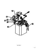
Страница 36: ...FIGURE 14 Page 35 C A B D...
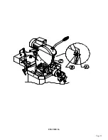
Страница 38: ...Page 37 FIGURE 15...
Страница 40: ...Page 39 FIGURE 16...
Страница 42: ...Page 41 FIGURE 17...
Страница 44: ...Page 43 FIGURE 18...
Страница 46: ...Page 45 FIGURE 19...
Страница 48: ...Page 47 FIGURE 20...
Страница 50: ...Page 49 FIGURE 20A...
Страница 58: ...Page 57 FIGURE 23...
Страница 60: ...FIGURE 24 Page 59...
Страница 62: ...Page 61 G 078000 60 RPM 230 Volt 1 Phase T S 078001 60 RPM 230 Volt 1 Phase E S FIGURE 25...
Страница 66: ...Page 65 FIGURE 27...
Страница 68: ...Page 67 FIGURE 28...
Страница 70: ...Page 69 FIGURE 29...
Страница 74: ...Page 73 FIGURE 31...
Страница 76: ...Page 75 FIGURE 32...
Страница 78: ...Page 77 FIGURE 33...
Страница 80: ...FIGURE 34 Page 79...
Страница 82: ...Page 81 FIGURE 35...
Страница 84: ...Page 83 FIGURE 36...
Страница 86: ...Page 85 FIGURE 37...
Страница 88: ...Page 87 FIGURE 38...
Страница 90: ...Page 89 FIGURE 39...


