


Page 30
7.0 OPTIONAL EQUIPMENT
7.1 POWER VISE
The power vise is an option that is normally ordered with the saw. It is not recommended as a retro-fit
in the field. The power vise allows automatic clamping of the material, which improves productivity and
reduces operator fatigue. The vise automatically clamps when the saw head is drawn down and releases
when the saw head returns.
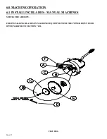
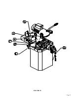
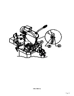
7.1A POWER VISE SET-UP AND MAINTENANCE
SEE FIGURE 11 ON THE FOLLOWING PAGE.
THE FOLLOWING ARE SET-UP AND MAINTENANCE INSTRUCTIONS FOR THE POWER VISE
OPTION (RETROFIT OR FACTORY INSTALLED):
1.
Before connecting the air supply to the saw, make sure that the filter/lubricating device (A) is full
of oil.
2.
Slide the shuttle valve (F) on the filter/lubricator device to the closed position.
3.
Connect the air supply to the shuttle valve. Make sure that the vise is clear and that the head is in
the UP position.
4.
Slide the shuttle valve in to open the valve. Whenever the shuttle valve is closed, it bleeds the air
pressure out of the system automatically.
5.
Adjust the air pressure regulator (G). 90 PSI (6.2 BAR) is the minimum operating pressure. 105
PSI (7.2 BAR) is the maximum.
6.
Before powering the saw, pull the head down several times, to make sure that the four way valve
(H) and the lubricating device (A) are adjusted properly and that the air pressure setting remains
constant.
7.
The four way valve should activate the vise at the beginning of the down stroke and release it at
the top of the return stroke. The four way valve is adjusted with the set screw (B) in the valve arm,
just above the roller.
8.
The lubricating device (A) should release one drop of oil every 5 to 10 cycles. On top of the
lubricating device is a clear plastic dome with a small copper tube inside. The oil should drop
out of the copper tube. The lubricating device is adjusted by turning the knob (C) on the top of the
lubricator.
9.
To add oil to the lubricating device, disconnect the air supply and remove the plastic bowl. The
bowl is threaded and unscrews from the body. Fill the bowl approximately 3/4 full of oil designed
for air lubricators and screw it back on the lubricator.
Содержание CPO-275
Страница 8: ...Page 7 FIGURE 1...
Страница 10: ...Page 9 FIGURE 2...
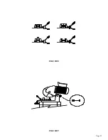
Страница 13: ...Page 12 MANUAL OR PK W TRIGGER SWITCH FIGURE 3 1...
Страница 14: ...Page 13 PKPD W EMERGENCY STOP FIGURE 3 2...
Страница 15: ...Page 14 1 PHASE MOTOR W TRIGGER SWITCH FIGURE 3 3...
Страница 16: ...Page 15 1 PHASE MOTOR W E STOP SERIAL S B3431 UP FIGURE 3 4...
Страница 22: ...Page 21 FIGURE 5A...
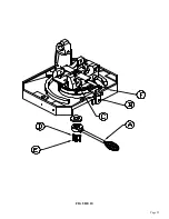
Страница 28: ...Page 27 FIGURE 8 FIGURE 9...
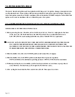
Страница 30: ...Page 29 FIGURE 10...
Страница 36: ...FIGURE 14 Page 35 C A B D...
Страница 38: ...Page 37 FIGURE 15...
Страница 40: ...Page 39 FIGURE 16...
Страница 42: ...Page 41 FIGURE 17...
Страница 44: ...Page 43 FIGURE 18...
Страница 46: ...Page 45 FIGURE 19...
Страница 48: ...Page 47 FIGURE 20...
Страница 50: ...Page 49 FIGURE 20A...
Страница 58: ...Page 57 FIGURE 23...
Страница 60: ...FIGURE 24 Page 59...
Страница 62: ...Page 61 G 078000 60 RPM 230 Volt 1 Phase T S 078001 60 RPM 230 Volt 1 Phase E S FIGURE 25...
Страница 66: ...Page 65 FIGURE 27...
Страница 68: ...Page 67 FIGURE 28...
Страница 70: ...Page 69 FIGURE 29...
Страница 74: ...Page 73 FIGURE 31...
Страница 76: ...Page 75 FIGURE 32...
Страница 78: ...Page 77 FIGURE 33...
Страница 80: ...FIGURE 34 Page 79...
Страница 82: ...Page 81 FIGURE 35...
Страница 84: ...Page 83 FIGURE 36...
Страница 86: ...Page 85 FIGURE 37...
Страница 88: ...Page 87 FIGURE 38...
Страница 90: ...Page 89 FIGURE 39...