


Page 28
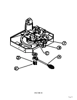
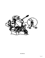
6.5 MITER LOCKING DEVICE
SEE FIGURE 10 ON THE FOLLOWING PAGE.
All models manufactured for domestic sales are equipped with a miter locking device which allows
quick set-up for mitering at 45 degrees, left and right, and 90 degrees for straight cutting. A miter
locking device is available as an option for models manufactured for international sales.
TO USE THE MITER LOCKING DEVICE:
1.
Unlock the tension handle (A).
2.
Push the miter lock release handle (B).
3.
Turn the head in the direction that you want to miter.
4.
Release the miter lock handle and continue turning the head until the pin snaps into the slot.
5.
Then, re-lock the tension handle. When locking the tension handle, do not over-tighten.
6.
The miter locking device can be fine adjusted if it does not stop at an exact 45. Loosen the
mounting bolts (F) and adjust the complete miter lock, left or right, to the desired position.
IF YOU WANT TO CUT MITERS OTHER THAN 45 DEGREES:
1.
Unlock the tension handle (A).
2.
Push the miter lock release handle (B) and turn the head to the desired angle by using the scale on
the saw.
NOTE: THE SCALE IS READ ON THE RIGHT SIDE OF THE VISE AT POINT (C), NOT IN
THE CENTER.
3.
Re-lock the tension handle (A). After a period of time, the tension handle (A) may need to be
adjusted if the head will not remain in the position that it was previously set.
TO RE-SET THE TENSION HANDLE:
1.
Remove the access panel on the back of the machine base.
2.
Move the tension handle (A) to its unlocked position.
3.
Loosen the jam nuts (D) on the adjustment bolts (E) and tighten the bolts finger tight, plus 1/4 of a
turn.
4.
Work the tension handle several times and re-tighten the adjusting bolts, if necessary.
5.
Re-tighten the jam nuts (D).
Содержание CPO-275
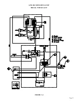
Страница 8: ...Page 7 FIGURE 1...
Страница 10: ...Page 9 FIGURE 2...
Страница 13: ...Page 12 MANUAL OR PK W TRIGGER SWITCH FIGURE 3 1...
Страница 14: ...Page 13 PKPD W EMERGENCY STOP FIGURE 3 2...
Страница 15: ...Page 14 1 PHASE MOTOR W TRIGGER SWITCH FIGURE 3 3...
Страница 16: ...Page 15 1 PHASE MOTOR W E STOP SERIAL S B3431 UP FIGURE 3 4...
Страница 22: ...Page 21 FIGURE 5A...
Страница 28: ...Page 27 FIGURE 8 FIGURE 9...
Страница 30: ...Page 29 FIGURE 10...
Страница 36: ...FIGURE 14 Page 35 C A B D...
Страница 38: ...Page 37 FIGURE 15...
Страница 40: ...Page 39 FIGURE 16...
Страница 42: ...Page 41 FIGURE 17...
Страница 44: ...Page 43 FIGURE 18...
Страница 46: ...Page 45 FIGURE 19...
Страница 48: ...Page 47 FIGURE 20...
Страница 50: ...Page 49 FIGURE 20A...
Страница 58: ...Page 57 FIGURE 23...
Страница 60: ...FIGURE 24 Page 59...
Страница 62: ...Page 61 G 078000 60 RPM 230 Volt 1 Phase T S 078001 60 RPM 230 Volt 1 Phase E S FIGURE 25...
Страница 66: ...Page 65 FIGURE 27...
Страница 68: ...Page 67 FIGURE 28...
Страница 70: ...Page 69 FIGURE 29...
Страница 74: ...Page 73 FIGURE 31...
Страница 76: ...Page 75 FIGURE 32...
Страница 78: ...Page 77 FIGURE 33...
Страница 80: ...FIGURE 34 Page 79...
Страница 82: ...Page 81 FIGURE 35...
Страница 84: ...Page 83 FIGURE 36...
Страница 86: ...Page 85 FIGURE 37...
Страница 88: ...Page 87 FIGURE 38...
Страница 90: ...Page 89 FIGURE 39...