Scotchman CPO-275 Скачать руководство пользователя страница 26

Page 25

6.3 SELECTING THE PROPER BLADE AND CUTTING SPEED

In cold sawing, there is no such thing as a general purpose blade. To achieve the best results from your 

saw, proper blade selection is important. Each saw is shipped with a pitch (number of teeth) calculator, 

which will help to determine the proper blade for your application.

When sawing flat stock or rectangular solid sections, determine the thickest section that will be cut and 

use the equivalent square size on the pitch calculator to determine the proper blade.

The CPO-350 Variable Speed saw is designed to use a maximum 14 inch (350mm) diameter blade. We 

recommend using smaller diameter blades if your application does not require the maximum diameter. 

Using smaller diameter blades reduces the surface feet per minute and smaller blades provide greater 

rigidity. Smaller diameter blades available from stock for this machine are a 12-1/2 inch (315mm) and a 

10-3/4 inch (275mm). For available tooth styles in stock, REFER TO SECTION 11.0. 

The chart below gives the surface feet per minute for the various diameter blades.

BLADE DIAMETER

SURFACE FEET PER MINUTE

INCH

MM


 RPM’S 

11

35

88

176

10-3/4

275

31

99

247

500

12-1/2

315

36

114

287

572

14

350

41

128

322

646

The proper blade speed is also important. The CPO-350 Variable Speed has an RPM range from 11 to

176. The heavier the material, the lower the RPM. The lighter the material, the higher the RPM.

The HT model (60-120 RPM) is recommended primarily for thin wall tube up to 1/8 of an inch (3mm) 

wall thickness and nonferrous materials. The low speed (60 RPM) should be used for tubes with wall 

thicknesses of one hundred thousandths (.025mm) and thicker and for solid sections of nonferrous 

materials. The High speed (120 RPM) is recommended for thin walled tubes and nonferrous tubes and 

profiles. Some materials will require test cuts at both speeds to determine the best speed for the 

application.

The LT model (30-60 RPM) is recommended for cutting solid sections, alloy tubes and nonferrous 

materials. The Low speed (30 RPM) is recommended for solid sections of mild steel and alloy tubes. The 

high speed (60 RPM) is recommended for tubes and nonferrous materials. As with the HT model, some 

materials will require test cuts to determine the best speed. 

Содержание CPO-275

Страница 1: ...You have downloaded a manual for our MODEL CPO 275 COLD SAW Please download our Cold Sawing Guide too Read both the manual and guide before operating this saw...

Страница 2: ...www scotchman com MODEL CPO 275 COLD SAW Printed May 2021 SCOTCHMAN IND 180 E US HWY 14 PO BOX 850 PHILIP SD 57567 Phone 1 800 843 8844 S N B39130421 AFTER...

Страница 3: ...nce 20 6 0 MACHINE OPERATION 22 6 1 Installing Blades 22 6 2 Saw Capacities 24 6 3 Selecting The Proper Blade Cutting Speed 25 6 4 Material Clamping 26 6 5 Miter Locking Device 28 7 0 OPTIONAL EQUIPME...

Страница 4: ...2 Vise Assembly 56 9 3 Guard Assembly 58 9 4 Motor Assembly 60 9 5 Electrical 62 9 6 Coolant System Base 64 9 7 Cast Base Pedestal 66 9 8 Material Stop 30 Inch 76 CM 68 10 0 OPTIONAL EQUIPMENT PARTS...

Страница 5: ...noises that are associated with abrasive cutoff saws Cold saws also offer the advantage of blades that can be re sharpened until the diameter of the blade will no longer cut through the material The s...

Страница 6: ...ective goods This warranty does not apply to machines and or components which have been altered changed or modified in any way or subjected to abuse and abnormal use inadequate maintenance and lubrica...

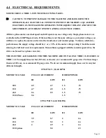
Страница 7: ...HE POWER VISE OR THE POWER DOWN FEED OPTION READ ALL SECTIONS CONCERNING THESE OPTIONS BEFORE OPERATING THE SAW 4 1 PHYSICAL DIMENSIONS SEE FIGURE 1 ON THE FOLLOWING PAGE DIMENSIONS INCHES CM A HEIGHT...

Страница 8: ...Page 7 FIGURE 1...

Страница 9: ...d locked in the DOWN position Before lifting the machine release the head on manual and power vise saws by cutting the banding strap and allowing it to move to the UP position On machines equipped wit...

Страница 10: ...Page 9 FIGURE 2...

Страница 11: ...from the electrical control box and connect the trigger switch wires Remove any other packing material and draw the saw head to its DOWN position to make sure that the guard opens properly The guard s...

Страница 12: ...y performance the supply voltage should be or 10 of the motor voltage rating Check the motor data tag for full load current requirements On machines equipped with the variable speed drive the drive ca...

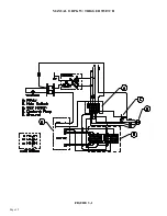
Страница 13: ...Page 12 MANUAL OR PK W TRIGGER SWITCH FIGURE 3 1...

Страница 14: ...Page 13 PKPD W EMERGENCY STOP FIGURE 3 2...

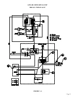
Страница 15: ...Page 14 1 PHASE MOTOR W TRIGGER SWITCH FIGURE 3 3...

Страница 16: ...Page 15 1 PHASE MOTOR W E STOP SERIAL S B3431 UP FIGURE 3 4...

Страница 17: ...tion and use the trigger switch mounted in the draw handle to start the motor Always turn the HI LOW switch to the OFF position when the saw is not in use On machines equipped with a 1 phase motor use...

Страница 18: ...unting bolts and rivet joints in the guard and linkage for wear Replace worn parts promptly USE THE FOLLOWING STEPS TO ADJUST THE BLADE GUARD 1 Turn the power OFF and disconnect from the power source...

Страница 19: ...0 3 liters One gallon of coolant is shipped with the saw For normal cutting it should be mixed in a ratio of one part coolant to seven parts water In conditions of heavier cutting the ratio of water s...

Страница 20: ...ipped with the power vise or power down feed options SEE SECTIONS 7 1 THRU 7 2 for additional information Since every application is different each user must design and implement a scheduled maintenan...

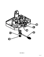
Страница 21: ...r to the machine is off 3 Remove the four bolts J and remove the pump from the machine 4 Remove the coolant line H and the fitting G Clean any sludge out of the line and fittings 5 Remove the three bo...

Страница 22: ...Page 21 FIGURE 5A...

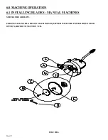
Страница 23: ...Page 22 6 0 MACHINE OPERATION 6 1 INSTALLING BLADES MANUAL MACHINES SEE FIGURE 6 BELOW FOR INSTALLING BLADES ON MACHINES EQUIPPED WITH THE POWER DOWN FEED OPTION REFER TO SECTION 7 2D FIGURE 6...

Страница 24: ...holes line up to the holes in the spindle 5 Replace the blade flange and start the bolt into the spindle 6 Before locking the blade in position the back lash must be taken up To take up the back lash...

Страница 25: ...ees Page 24 Figure 7 CPO 275 CAPACITIES WITH MAXIMUM DIAMETER BLADES 275 MM 90 060330 INCHES MM INCHES MM INCHES MM INCHES MM INCHES MM INCHES MM INCHES MM 45 03 21 3 3 8 86 2 51 3 X 3 76 X 76 2 X 2 5...

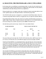
Страница 26: ...rface feet per minute for the various diameter blades BLADE DIAMETER SURFACE FEET PER MINUTE INCH MM RPM S 11 35 88 176 10 3 4 275 31 99 247 500 12 1 2 315 36 114 287 572 14 350 41 128 322 646 The pro...

Страница 27: ...d them When trimming or cutting very short pieces that do not extend into both sides of the vise place a piece of material the same size in the unused side of the vise to insure uniform clamping When...

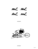
Страница 28: ...Page 27 FIGURE 8 FIGURE 9...

Страница 29: ...ted if it does not stop at an exact 45 Loosen the mounting bolts F and adjust the complete miter lock left or right to the desired position IF YOU WANT TO CUT MITERS OTHER THAN 45 DEGREES 1 Unlock the...

Страница 30: ...Page 29 FIGURE 10...

Страница 31: ...losed it bleeds the air pressure out of the system automatically 5 Adjust the air pressure regulator G 90 PSI 6 2 BAR is the minimum operating pressure 105 PSI 7 2 BAR is the maximum 6 Before powering...

Страница 32: ...al in the vise 3 Crank the vise closed to within approximately 1 8 of an inch 3mm from the material and relock the locking collar D Failure to lock the locking collar may allow the vise to vibrate ope...

Страница 33: ...rom the base of the vise 4 Remove the guide pins D out through the back of the vise The head must be moved to the miter position in each direction to remove the pins 5 Lift the complete vise off of th...

Страница 34: ...lar C from the front of the spindle 4 Remove the two bolts D from the front vise casting that holds the air cylinder on 5 Unscrew the air cylinder from the spindle 6 Remove the eight socket head cap s...

Страница 35: ...ommended oil to use is SAE 10W ISO 32 non foaming hydraulic oil such as Mobil DTE 10 or equivalent CAUTION ALWAYS DISCONNECT THE AIR SUPPLY BEFORE REMOVING THE FILLER PLUG FROM THE RESERVOIR IF THE FI...

Страница 36: ...FIGURE 14 Page 35 C A B D...

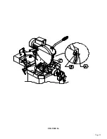
Страница 37: ...control valve 5 Loosen the handle on the upper collar A and slide the collar down until it contacts the limit switch G 6 To make sure that the settings are correct open the flow control valve D and c...

Страница 38: ...Page 37 FIGURE 15...

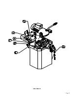
Страница 39: ...2 With the saw head in the UP position loosen the bolt A in the guard stop B 3 Raise the movable section of the guard C so that it just clears the vise jaws by no more than 1 8 of an inch 3mm 4 Adjust...

Страница 40: ...Page 39 FIGURE 16...

Страница 41: ...the blade Make sure that the pin holes line up to the holes in the spindle 6 Replace the blade flange and start the bolt into the spindle 7 Before locking the blade in position the back lash must be t...

Страница 42: ...Page 41 FIGURE 17...

Страница 43: ...check valve V Clean or replace it 2 THE HEAD FEEDS FAST WITH NO CONTROL HEAD BANGING UP LOW OIL LEVEL Add oil hydraulic oil 3 THE HEAD STOPS AND DOES NOT FEED THROUGH THE MATERIAL Adjust the Down Fee...

Страница 44: ...Page 43 FIGURE 18...

Страница 45: ...y A with the remaining 10 x 30mm hex head bolts 3 Place the two remaining 10 x 80mm hex bolts through the end of the rail assembly and lock them in place with the hex nuts 4 Thread another nut on each...

Страница 46: ...Page 45 FIGURE 19...

Страница 47: ...them in place with the hex nuts 4 Thread another nut on each bolt and attach the track to the support bracket with the remaining two 10mm hex nuts 5 Space the rollers along the rail at an even spacing...

Страница 48: ...Page 47 FIGURE 20...

Страница 49: ...ut disconnect switch is available for this machine if your plant is not equipped with lock out capabilities The switch mounts on the base of the saw and is shipped complete with all of the necessary p...

Страница 50: ...Page 49 FIGURE 20A...

Страница 51: ...s correct the switch energizes and the motor still will not run contact your local dealer or the factory 2 THE SAW MOTOR RUNS BUT DOES NOT HAVE ADEQUATE POWER A Make sure that the supply voltage and p...

Страница 52: ...d the blade clean and free from nicks Any contamination or nicks on the flange spindle or the blade will cause the blade to run out of alignment 7 Always remove the back lash when installing a blade F...

Страница 53: ...e level is less than 3 inches the fluid will not flow C Check the reservoir for contamination or sludge build up that may be blocking the pump inlet D Remove the coolant line from the guard and make s...

Страница 54: ...access holes in the guard 4 Remove the spindle shaft D with a slide hammer This shaft can also be removed by driving it out of the head casting with a brass drift pin 5 Remove the snap ring E 6 The b...

Страница 55: ...sting N 077152 Sight Gauge O 077002 Handle OA 077001 Switch P 077000 Draw Handle Complete Inc O OA P Q Q 073210 M 20 Jam Nut R 677862 Grease Nipple S 221212 M 10 x 30 SHCS T 077104 Pivot Shaft T1 0771...

Страница 56: ...073108 M 8 Lock Washer GG 221120 M 8 x 25 SHCS HH 080193 M 8 Blade Allen Wrench Not pictured II 077630 Vent JJ 073692 Eye Bolt Not pictured KK 077107 Complete Head Assembly LL 073106 M 6 Lock Washers...

Страница 57: ...ART DESCRIPTION M 10 x 35 SHCS Cast Grip Cheek Rear Vise Jaw Right M 10 Hex Nut Guide Shaft Seal 275 Vise Base Sales Dowel Pin Screw End Pressure Plate Tension Nut Assembly Includes L M Tension Nut M...

Страница 58: ...Page 57 FIGURE 23...

Страница 59: ...ON Complete Guard Assembly M 8 x 25 SHCS Spacer Ring Thick Hinged Cap Front Spacer Ring Thin Hinged Cap Rear Bushing Snap Ring M 8 Plastic Washer Coupling Rod Rivet Self Locking Ring Coupling Rod M 6...

Страница 60: ...FIGURE 24 Page 59...

Страница 61: ...C Safety Ring Complete Motors Without Switches 076968 076970 076962 076964 676958 676960 076960 60 120 RPM 230 Volt 60 120 RPM 460 Volt 30 60 RPM 230 Volt 30 60 RPM 460 Volt 60 120 RPM 575 Volt 30 60...

Страница 62: ...Page 61 G 078000 60 RPM 230 Volt 1 Phase T S 078001 60 RPM 230 Volt 1 Phase E S FIGURE 25...

Страница 63: ...SEL SW KNB T0 Motor Cable Pump Cable M13 5 Liquid Cord Conn M5 X 12 SHCS Transformer 24V 208 230 460 Transformer 575 Volt 3 4 Liquid Type Connector ON OFF Switch 220V 1PH for PD or PK PD Saw Fuse Com...

Страница 64: ...FIGURE 26 Page 63 T M P J A C D E F H I K L O Q R S B N G ELECTRICAL HAZARD Turn off power and lock out before servicing DANGER...

Страница 65: ...230V 3PH Pump A3 060200 230V 3PH Pump Assembly A4 060158 460V 3PH Pump A5 060201 460V 3PH Pump Assembly A6 060160 575V Coolant Pump Assemblies include A G I B 060152 Impeller C 060157 End Cap D 06015...

Страница 66: ...Page 65 FIGURE 27...

Страница 67: ...073660 M 8 x 12 HHCS J 073420 M 8 x 25 SHCS K 077212 Upper Spring Mount L 077211 Return Spring M 677109 Adjustment Lock N 221212 M 10 x 30 SHCS O 677863 M 10 x 120 HHCS P 221210 M 10 x 25 SHCS Q 0772...

Страница 68: ...Page 67 FIGURE 28...

Страница 69: ...TEM PART DESCRIPTION 1 760115 CPO Base Cabinet 2 760114 CPO Chip Drawer 3 760115 8 Pump Mounting Bracket 4 073420 M 8 x 16 DIN912 SHCS 5 215013 M 8 Greer Nut 6 060170 1 8 Clearflex Plastic 7 060175 Re...

Страница 70: ...Page 69 FIGURE 29...

Страница 71: ...Boss N 077400 Handle O 077121 M 20 Jam Nut P 221002 M 5 x 12 SHCS Q 077742 1 4 Male Swivel R 060501 5 16 Black Tube S 077183 Cord Connector T 077430 Four Way Valve U 060501 5 16 Black Tube V 077542 L...

Страница 72: ...Page 71 GG 077409 Lock Ring HH 060270 Covering Cap II 077310 Seal 077412 Complete Air Cylinder 076371 Cylinder Seal Kit Includes F G K 677878 Complete Air Vise FIGURE 30...

Страница 73: ...H 123120 1 8 Cotter Pin I 078518 Stroke Adjustment Stop Upper J 078518 Stroke Adjustment Stop Lower K 080062 Stroke Adjustment Handle L 077715 Pivot Bolt M 077515 Festo Cylinder M N O P Q S T V M1 07...

Страница 74: ...Page 73 FIGURE 31...

Страница 75: ...045667 Two Station Valve DC K1 060040 Two Station Valve AC L 077777 3 8 NPT Plug M 060104 Cord Grip N N A O 077719 Slide Valve P 077737 1 4 NPT x 90 Degrees Q 077553 Filter Regulator Q1 077554 Bowl Lu...

Страница 76: ...Page 75 FIGURE 32...

Страница 77: ...5 Mounting Plate D 075210 Mounting Strip E 073440 M 4 x 6 SHCS F 078104 End Bracket I 078456 M 4 x 6 Terminal Block J 078457 Jumper K 060044 24 Volt Relay L 060104 Cord Grip M 660456 Cord 90 N 158202...

Страница 78: ...Page 77 FIGURE 33...

Страница 79: ...64 214005 070001 070002 DESCRIPTION 275PD Guard Sales M8 x 25 SHCS Movable Guard Snap Ring Spacer Nylon PD Guard Stop M6 x 12 Knob Hub 9 16 x 85 Coolant Line Hose Barb Valve Blade Rotation Decal Warni...

Страница 80: ...FIGURE 34 Page 79...

Страница 81: ...30 M 10 x 100 HHCS D 221210 M 10 x 25 HHCS E 029245 Roller F 076938 Optional Guide Assembly G 229225 M 10 x 70 Shoulder Bolt H 043003 Guide Roller I 214012 M 10 Washer J 221120 M 8 x 25 SHCS K 076943...

Страница 82: ...Page 81 FIGURE 35...

Страница 83: ...130212 3 8 x 16 x 1 1 4 C Bolt 10 029272 Mounting Bracket 11 114011 5 16 Washer 12 108012 3 8 x 16 Hex Nut 14 203212 M 10 x 30 HHCS 15 204230 M 10 X 100 HHCS 60 RIGHT HAND 3 029226 Tape 4 029232 RH Qu...

Страница 84: ...Page 83 FIGURE 36...

Страница 85: ...tic Coolant Special Mix Coolant Special Mix Coolant Air Line Lubricant Air Line Lubricant 10 6 LOCK OUT DISCONNECT SWITCH ITEM PART A B C D E F G H 563025 562250 N A 563441 108010 158200 224205 114010...

Страница 86: ...Page 85 FIGURE 37...

Страница 87: ...lete Laser Assembly 2 065003 Laser Cover 3 065005 Laser Mounting Bracket 4 065007 Laser Pivot 5 214012 M 10 Washer 6 201200 M 10 x 12 HHCS 7 221007 M 4 x 8 SHCS 8 046094 Medium Wire Clip 9 Laser Trans...

Страница 88: ...Page 87 FIGURE 38...

Страница 89: ...AL STOP 30 INCH 72 CM ITEM PART DESCRIPTION A 677436 Stop Clamp Includes D B 060315 Stop Shaft C 060310 Shaft D 073460 M 10 x 16 SHCS E 076930 Complete Ass y A B C F G F 080193 M 8 Wrench Not Shown G...

Страница 90: ...Page 89 FIGURE 39...

Страница 91: ...250mm Dia 100 Tooth 10 Inch 250mm Dia 120 Tooth 10 Inch 250mm Dia 150 Tooth 10 Inch 250mm Dia 180 Tooth 10 Inch 250mm Dia 240 Tooth 10 Inch 250mm Dia 90 Tooth 10 75 Inch 275mm Dia 100 Tooth 10 75 Inch...

Страница 92: ...th form This grind is used on blades that have 220 teeth or less This style is used for a wide range of materials from solid sections of nonferrous materials to heavy wall tubes and solid sections of...

Страница 93: ...old Sawing Guide Scotchman Ind 180 E US Hwy 14 Philip SD 57567 1 605 859 2542 www scotchman com The Worlds Best Cold Saws Ironworkers Proudly Made In America www scotchman com 10 8 20 METAL FABRICATIN...

Страница 94: ...WHU DQG DOPRVW EXUU IUHH FXW FRPSDUHG WR RWKHU ZD V RI VDZLQJ DQG FXWV PRUH DFFXUDWHO SHU LD LQFK XQGHU LGHDO FRQGLWLRQV 6FRWFKPDQ QG PDQXIDFWXUHV PDQ FROG VDZ PRGHOV IURP PDQXDO DQG VHPL DXWRPDWLF VD...

Страница 95: ...FK ROG VDZ EODGHV DUH ROORZ URXQG ZKLFK VLPSO PHDQV WKH DUH WKLFNHU RQ WKH ULP DQG JUDGXDOO WDSHU WR D WKLQQHU WKLFNQHVV WR WKH FHQWHU KXE RI WKH EODGH 7KLV DOORZV WKH EODGH WR SDVV WKURXJK WKH PDWHUL...

Страница 96: ...LEXWHV 7KH VKHHWV WKRURXJKO H SODLQ HDFK DQG KHOS VKRZ ZKDW WKH SURSHU EODGH LV IRU WKH VL H DQG W SH RI PDWHULDO WR EH FXW KHQ WKH SURSHU 3LWFK LV GHWHUPLQHG WKHQ WKH QXPEHU RI WHHWK IRU WKH EODGH FD...

Страница 97: ...ODW RX VKRXOG LQFUHDVH WKH SLWFK IURP PP WR PP RU H DPSOH LI RX FXW D PLOG VWHHO URXQG ZDOO WXEH RU D VTXDUH WXEH RQ WKH GLDJRQDO SRLQW WR SRLQW ZLWK D GLDPHWHU EODGH D WRRWK EODGH LV XVHG DQG KDV D P...

Страница 98: ...HHWK 7HHWK LQ PP LQ PP LQ PP LQ PP 7HHWK LQ PP LQ PP 7HHWK 7HHWK 7HHWK 7HHWK 7HHWK 0 7 5 6 2 7 7 3 7 5RXQG 7XELQJ QJOH 6TXDUH XW RQ WKH GLDJRQDO 6TXDUH 7XEH XW FURVV WKH ODW QFUHDVH 3LWFK PP PP OHVV W...

Страница 99: ...V 7KH 7 PRWRU ZRXOG EH XVHG WR FXW VROLGV RU KHDY ZDOOHG WXELQJ 6FRWFKPDQ DOVR KDV DQ RSWLRQDO 9DULDEOH 6SHHG ULYH WKDW FDQ EH DGGHG VR WKH EODGH V USP FDQ EH ILQH WXQHG WR ZKDW RX UH FXWWLQJ H DOVR K...

Страница 100: ...UV DQG FDXVH WKH PRVW SUREOHPV H FDOO WKHP DFNODVK DQG LUW ODQJH 6 7KH VDZ EODGH LV GULYHQ E WKH SLQV LQ WKH IODQJH KHQ FKDQJLQJ EODGHV WKH EDFNODVK PXVW EH UHPRYHG RU 7DNHQ 8S DQG LV YHU VLPSOH WR GR...

Страница 101: ...HFLDOO 3LFN 8S Q WKH LUW ODQJH SLFWXUH RX FDQ VHH WKH FLUFOHG VKLQ VSRWV DUH ZKHUH PHWDO FKLSV ZHUH LQ EHWZHHQ WKH VSLQGOH DQG WKH EODGH DQG ZRUH DZD WKH EODFN R LGH FRDWLQJ DV VHHQ FLUFOHG LQ WKH SLF...

Страница 102: ...N LV ULSSHG RXW DQG WKH EODGH LV EURNHQ 3LFN XS ZKHQ FDXJKW HDUO LV EHVW UHPRYHG E UXEELQJ LW RII ZLWK D KDQG KHOG KRQH VWRQH 127 ZLWK D SRZHU WRRO I RX WDNH WRR PXFK RII WKHQ RX PDNH WKH EODGH WKLQQH...

Страница 103: ...WKH SURSHU VWUHQJWK HDN FRRODQW ZLOO VKRUWHQ EODGH OLIH DQG FDQ FDXVH 3LFN 8S 5XVW LQGLFDWHV ZHDN FRRODQW DQG FDQ FDXVH SUREOHPV DV ZHOO DV UXLQ VDZ EODGHV E GDPDJLQJ WKH EODGH FRDWLQJ DQG SDUWV RI WK...

Страница 104: ...3LFN 8S ERWK VLGHV RI EODGH 0DWHULDO 6OLSSHG LQ 9LVH 20021 352 06 DFN DVK EUHDN LV WKUX SLQ KROH LUW ODQJH VKLQ VSRWV 5EQVEJOCP PFU 75 Y 2JKNKR 5 YYY UEQVEJOCP EQO 3DJH...

Страница 105: ...ATERIAL TOLERANCE UNLESS SPECIFIED 5 12 16 Jason S None Most Common is HSS COLD SAW BLADE TOOTH GEOMETRY Tooth Geometry Cold Saw Blade Proper Tooth Shape 3 1 Nice Round Gullet is Ideal 16 18 Hook Angl...

Страница 106: ...the Material SOLID Slower RPM Rounds usually cut better with closer to 5 teeth in the material Squares usually cut better with closer to 3 teeth in the material Slower RPM Pitch should be Less than th...

Страница 107: ...have a Notch Notches are Offset from Each Other and breaks up the Chip made during the Cut Typically used on Blades with a 4 5 Pitch or Less Generally 220 Teeth or more More Teeth Smaller Pitch Best f...

Отзывы: