


Page 23
⌦
CAUTION: USE ONLY HIGH SPEED STEEL BLADES DESIGNED FOR THIS MACHINE.
DO NOT MODIFY ANY BLADE TO FIT THIS MACHINE. DO NOT USE BLADES
DESIGNED FOR THIS MACHINE ON ANY OTHER EQUIPMENT.
The CPO-275 saw is designed to use a maximum 10-3/4 inch (275mm) diameter blade. The arbor size is
32mm with two 8mm pins spaced at 45mm.
BEFORE INSTALLING THE BLADE, make sure that the power to the machine is disconnected.
USE THE FOLLOWING STEPS TO INSTALL A BLADE:
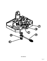
(An 8mm hex key wrench (D), shipped with each machine, is required to change blades.)
1.
Remove the bolt (A) from the guard linkage with the hex key wrench (D) and manually open the
guard.
2.
Remove the blade bolt (B) through the center hole in the blade guard.
3.
Remove the blade flange (C).
4.
Install the blade. Make sure that the pin holes line up to the holes in the spindle.
5.
Replace the blade flange and start the bolt into the spindle.
6.
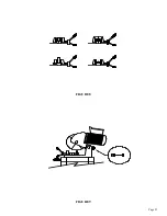
Before locking the blade in position, the back lash must be taken up. To take up the back lash,
rotate the bottom of the blade towards you until it seats against the drive pins.
⌦
CAUTION: THE BLADES ARE VERY SHARP AND CARE MUST BE TAKEN WHEN
REMOVING THE BACK LASH. DO NOT GRIP THE CUTTING EDGE OF THE BLADE
BARE HANDED. THE BACK LASH MUST BE TAKEN UP EVERY TIME A BLADE IS
CHANGED.
7.
After taking up the back lash, tighten the blade bolt (B).
8.
Break in the saw blade. The teeth on new or re-sharpened blades have a sharp edge and should be
manually fed through the first three or four cuts very slowly, before starting normal cutting.
Besides taking up the back lash and breaking in the blade, it is very important to keep the blade
flange, the spindle and the blade clean and free from nicks and chips. Failure to do these things
will result in broken or damaged blades.
Содержание CPO-275
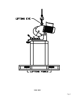
Страница 8: ...Page 7 FIGURE 1...
Страница 10: ...Page 9 FIGURE 2...
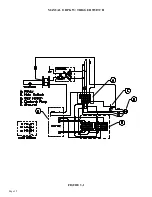
Страница 13: ...Page 12 MANUAL OR PK W TRIGGER SWITCH FIGURE 3 1...
Страница 14: ...Page 13 PKPD W EMERGENCY STOP FIGURE 3 2...
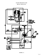
Страница 15: ...Page 14 1 PHASE MOTOR W TRIGGER SWITCH FIGURE 3 3...
Страница 16: ...Page 15 1 PHASE MOTOR W E STOP SERIAL S B3431 UP FIGURE 3 4...
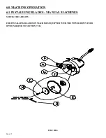
Страница 22: ...Page 21 FIGURE 5A...
Страница 28: ...Page 27 FIGURE 8 FIGURE 9...
Страница 30: ...Page 29 FIGURE 10...
Страница 36: ...FIGURE 14 Page 35 C A B D...
Страница 38: ...Page 37 FIGURE 15...
Страница 40: ...Page 39 FIGURE 16...
Страница 42: ...Page 41 FIGURE 17...
Страница 44: ...Page 43 FIGURE 18...
Страница 46: ...Page 45 FIGURE 19...
Страница 48: ...Page 47 FIGURE 20...
Страница 50: ...Page 49 FIGURE 20A...
Страница 58: ...Page 57 FIGURE 23...
Страница 60: ...FIGURE 24 Page 59...
Страница 62: ...Page 61 G 078000 60 RPM 230 Volt 1 Phase T S 078001 60 RPM 230 Volt 1 Phase E S FIGURE 25...
Страница 66: ...Page 65 FIGURE 27...
Страница 68: ...Page 67 FIGURE 28...
Страница 70: ...Page 69 FIGURE 29...
Страница 74: ...Page 73 FIGURE 31...
Страница 76: ...Page 75 FIGURE 32...
Страница 78: ...Page 77 FIGURE 33...
Страница 80: ...FIGURE 34 Page 79...
Страница 82: ...Page 81 FIGURE 35...
Страница 84: ...Page 83 FIGURE 36...
Страница 86: ...Page 85 FIGURE 37...
Страница 88: ...Page 87 FIGURE 38...
Страница 90: ...Page 89 FIGURE 39...