


4.7 COOLANT SYSTEM
5.0 MAINTENANCE AND LUBRICATION
5.1 LUBRICATION
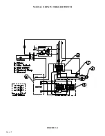
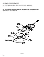
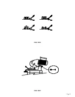
SEE FIGURE 5 BELOW.
Before operating the saw, grease the pivot pin (A) and apply penetrating oil to the vise spindle and
guides (B and C). Once a week, grease all of the pivot pins and oil all of the rivet connections on the
guard linkage (D). Clean the chips out of the vise at least once a day and apply penetrating oil to the
spindle and guide pins. Clear the chips with a brush or similar device. DO NOT use compressed air.
If your saw is equipped with a power vise or power down feed option, SEE SECTIONS 7.1 THRU 7.2,
for additional information.
FIGURE 5
Page 18
The coolant reservoir has a capacity of eight (8) gallons (30.3 liters). One gallon of coolant is shipped
with the saw. For normal cutting, it should be mixed in a ratio of one part coolant to seven parts water.
In conditions of heavier cutting, the ratio of water should be reduced to five parts. We recommend
using only pure, synthetic, water soluble cutting oils. There is a sieve screen in the back of the cast vise
base. To aid in adding coolant, the sieve screen can be removed with a screwdriver. Do not remove the
sieve screen if the base of the saw is not completely clean and free of chips. The plastic panel on the
back of the machine base can also be removed, to aid in adding coolant. We recommend pre-mixing
the coolant before adding it to the saw. When cutting alloy steels such as stainless steel, we recommend
a special mix coolant designed for these applications. For additional information on available coolants,
SEE SECTION 10.5.
D
B & C
A
Содержание CPO-275
Страница 8: ...Page 7 FIGURE 1...
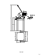
Страница 10: ...Page 9 FIGURE 2...
Страница 13: ...Page 12 MANUAL OR PK W TRIGGER SWITCH FIGURE 3 1...
Страница 14: ...Page 13 PKPD W EMERGENCY STOP FIGURE 3 2...
Страница 15: ...Page 14 1 PHASE MOTOR W TRIGGER SWITCH FIGURE 3 3...
Страница 16: ...Page 15 1 PHASE MOTOR W E STOP SERIAL S B3431 UP FIGURE 3 4...
Страница 22: ...Page 21 FIGURE 5A...
Страница 28: ...Page 27 FIGURE 8 FIGURE 9...
Страница 30: ...Page 29 FIGURE 10...
Страница 36: ...FIGURE 14 Page 35 C A B D...
Страница 38: ...Page 37 FIGURE 15...
Страница 40: ...Page 39 FIGURE 16...
Страница 42: ...Page 41 FIGURE 17...
Страница 44: ...Page 43 FIGURE 18...
Страница 46: ...Page 45 FIGURE 19...
Страница 48: ...Page 47 FIGURE 20...
Страница 50: ...Page 49 FIGURE 20A...
Страница 58: ...Page 57 FIGURE 23...
Страница 60: ...FIGURE 24 Page 59...
Страница 62: ...Page 61 G 078000 60 RPM 230 Volt 1 Phase T S 078001 60 RPM 230 Volt 1 Phase E S FIGURE 25...
Страница 66: ...Page 65 FIGURE 27...
Страница 68: ...Page 67 FIGURE 28...
Страница 70: ...Page 69 FIGURE 29...
Страница 74: ...Page 73 FIGURE 31...
Страница 76: ...Page 75 FIGURE 32...
Страница 78: ...Page 77 FIGURE 33...
Страница 80: ...FIGURE 34 Page 79...
Страница 82: ...Page 81 FIGURE 35...
Страница 84: ...Page 83 FIGURE 36...
Страница 86: ...Page 85 FIGURE 37...
Страница 88: ...Page 87 FIGURE 38...
Страница 90: ...Page 89 FIGURE 39...