


Page 10
4.3 PHYSICAL INSPECTION
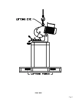
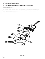
Once the machine is located, check it for any possible damage incurred in shipment. Remove the lifting
eyelet and install the draw handle.
⌦
CAUTION: DO NOT USE THE LIFTING EYELET FOR ANY MACHINES OTHER THAN
THIS SAW. MAKE SURE THAT THE DRAW HANDLE HAS A JAM NUT ON THE
THREADS BEFORE INSTALLING IT ON THE SAW. IF THE HANDLE IS INSTALLED
WITHOUT THE JAM NUT, IT MAY CONTACT THE GEARS INSIDE THE HEAD.
After the draw handle has been installed on manual and power vise machines, remove the cover from the
electrical control box and connect the trigger switch wires. Remove any other packing material and
draw the saw head to its DOWN position to make sure that the guard opens properly. The guard should
close completely when the head is up and open freely as the head travels down. If the guard is not
functioning properly, REFER TO SECTION 4.6 for the manual machines or SECTION 7.2C for
machines equipped with the power down feed option. With the head in the DOWN position, check the oil
level in the gear box through the sight glass in the casting just below the draw handle. If your saw is
equipped with either the power vise or the power down feed option, REFER TO SECTIONS 7.1 THRU
7.2, for additional information.
Содержание CPO-275
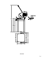
Страница 8: ...Page 7 FIGURE 1...
Страница 10: ...Page 9 FIGURE 2...
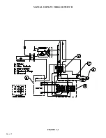
Страница 13: ...Page 12 MANUAL OR PK W TRIGGER SWITCH FIGURE 3 1...
Страница 14: ...Page 13 PKPD W EMERGENCY STOP FIGURE 3 2...
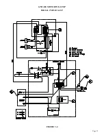
Страница 15: ...Page 14 1 PHASE MOTOR W TRIGGER SWITCH FIGURE 3 3...
Страница 16: ...Page 15 1 PHASE MOTOR W E STOP SERIAL S B3431 UP FIGURE 3 4...
Страница 22: ...Page 21 FIGURE 5A...
Страница 28: ...Page 27 FIGURE 8 FIGURE 9...
Страница 30: ...Page 29 FIGURE 10...
Страница 36: ...FIGURE 14 Page 35 C A B D...
Страница 38: ...Page 37 FIGURE 15...
Страница 40: ...Page 39 FIGURE 16...
Страница 42: ...Page 41 FIGURE 17...
Страница 44: ...Page 43 FIGURE 18...
Страница 46: ...Page 45 FIGURE 19...
Страница 48: ...Page 47 FIGURE 20...
Страница 50: ...Page 49 FIGURE 20A...
Страница 58: ...Page 57 FIGURE 23...
Страница 60: ...FIGURE 24 Page 59...
Страница 62: ...Page 61 G 078000 60 RPM 230 Volt 1 Phase T S 078001 60 RPM 230 Volt 1 Phase E S FIGURE 25...
Страница 66: ...Page 65 FIGURE 27...
Страница 68: ...Page 67 FIGURE 28...
Страница 70: ...Page 69 FIGURE 29...
Страница 74: ...Page 73 FIGURE 31...
Страница 76: ...Page 75 FIGURE 32...
Страница 78: ...Page 77 FIGURE 33...
Страница 80: ...FIGURE 34 Page 79...
Страница 82: ...Page 81 FIGURE 35...
Страница 84: ...Page 83 FIGURE 36...
Страница 86: ...Page 85 FIGURE 37...
Страница 88: ...Page 87 FIGURE 38...
Страница 90: ...Page 89 FIGURE 39...