


Date Code 20010625
Testing, Troubleshooting, and Commissioning
13-7
SEL-311L Instruction Manual
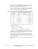
To test element accuracy, test the operate elements 87LOPA, 87LOPB, 87LOPC, 87LOP2, and
87LOPG, and also test the Alpha plane restraint elements R87LA, R87LB, R87LC, R87L2, and
R87LG. The relay trips when the restraint element is deasserted indicating that the Alpha plane
ratio falls outside the restraint region, and the operate element is asserted indicating the
differential current is above the differential current pickup setting.
This section details a test procedure suitable for testing the accuracy of the 87L elements in the
SEL-311L Relay.
The test procedure outlined below assumes factory default settings of:
E87L = 2
Two terminal protection
87LPP = 6
6 A secondary phase line current differential pickup setting
87L2P = 0.5
0.5 A secondary negative-sequence line current differential pickup
setting.
87LANG = 195
Restraint region subtends 195 degrees.
87LR = 6
Restraint region outside radius is six; inside radius is 1/6.
The test procedure alters those settings for the operate element tests to isolate the element under
test. The test procedure also disables the disturbance detector (EDD = N) to allow the use of
slowly changing currents.
SEL-311L Relay 87L Element Test Procedure
Purpose: Test the accuracy of phase and negative sequence 87L elements. Test the ground 87L
element using an identical procedure.
Test Outline: Test the phase 87L element accuracy for A-phase (B- and C-phase optional), then
test the negative-sequence 87L element accuracy. (Detailed test procedure follows.)
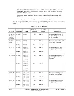
I: Test Phase 87L Element Accuracy
Test the phase operate element 87LOPA. To test the operate element, apply a low-
current internal three-phase fault, then increase the difference current until the relay
trips.
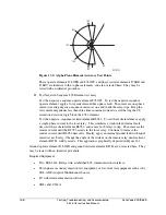
Test the phase restraint element R87LA. To test the restraint element, apply currents at
the local relay, with zero current applied to the remote relay. This simulates a weak-
infeed internal fault, deasserts restraint element R87LA, and causes both relays to trip.
Increase the magnitude of the currents at the remote relay until the restraint bit R87LA
asserts. Continue to increase the magnitude of the remote currents until restraint bit
R87LA deasserts. Repeat with various phase angles applied between local and remote
currents. Finally, apply an internal fault with equal current at each relay. Change the
angle of the current on the remote relay until restraint element R87LA in the local relay
solidly asserts. This approach is graphically depicted in Figure 13.2.
Содержание SEL-311L
Страница 6: ......
Страница 8: ......
Страница 26: ......
Страница 54: ......
Страница 144: ......
Страница 203: ...Date Code 20010625 Trip and Target Logic 5 27 SEL 311L Instruction Manual Figure 5 12 DCUB Logic ...
Страница 216: ......
Страница 252: ......
Страница 302: ......
Страница 338: ......
Страница 480: ......
Страница 484: ......
Страница 486: ......
Страница 502: ......
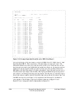
Страница 532: ...12 28 Standard Event Reports and SER Date Code 20010625 SEL 311L Instruction Manual 4 ...
Страница 552: ......
Страница 554: ......
Страница 574: ......
Страница 576: ......
Страница 596: ......
Страница 602: ......
Страница 628: ......
Страница 656: ......
Страница 662: ......
Страница 664: ......
Страница 688: ......
Страница 700: ......
Страница 716: ......
Страница 722: ......
Страница 734: ......