


4-10
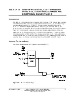
Loss-of-Potential, CCVT Transient Detection,
Date Code 20010625
Load-Encroachment, and Directional Element Logic
SEL-311L Instruction Manual
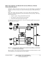
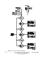
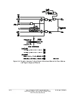
Note in Figure 4.5 that setting ORDER enables the directional elements. Set ORDER with any
combination of Q, V, and I, or set it to OFF. Setting choices Q, V, and I correspond to directional
elements as follows:
Q Negative-sequence voltage-polarized directional element
V Zero-sequence voltage-polarized directional element
I Channel IP current-polarized directional element
The order in which these directional elements are listed in setting ORDER determines the priority
in which they operate to provide
Best Choice Ground Directional™
logic control. See discussion
on setting ORDER in the following subsection
Directional Control Settings
.
ORDER = OFF does not form part of a valid combination. Either set ORDER = OFF or set some
combination of Q, V, and I.
When setting ORDER = OFF, the ground distance elements are disabled, and the residual ground
overcurrent elements are nondirectional, if they are enabled.
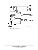
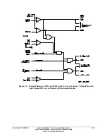
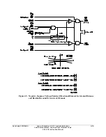
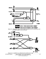
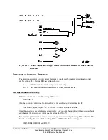
Directional Element Enables
Refer to Figure 4.5, Figure 4.6, and Figure 4.7.
The directional element enables, Relay Word bits 32QGE, 32VE, and 32IE have the following
correspondence to the directional elements:
32QGE
Negative-sequence voltage-polarized directional element
32VE
Zero-sequence voltage-polarized directional element
32IE
Channel IP current-polarized directional element
Note that Figure 4.6 has extra directional element enable 32QE, which is used in the logic that
controls phase distance elements (see Figure 4.14).
The settings involved with 32QGE, 32VE, and 32IE in Figure 4.6 and Figure 4.7 (e.g., settings
a2, k2, a0) are explained in the following subsection
Directional Control Settings
.
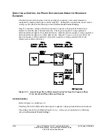
Best Choice Ground Directional
Logic
Refer to Figure 4.5 and Figure 4.8.
Relay Word bits 32QGE, 32VE, and 32IE and setting ORDER are used in the
Best Choice
Ground Directional
logic in Figure 4.8. The
Best Choice Ground Directional
logic determines
the order in which the directional element should be enabled to operate. The ground distance and
residual ground overcurrent elements set for directional control are then controlled by this
directional element.
Directional Elements
Refer to Figure 4.5, Figure 4.9, Figure 4.10, and Figure 4.11.
The enable output of
Best Choice Ground Directional
logic in Figure 4.8 determines which
directional element will run.
Содержание SEL-311L
Страница 6: ......
Страница 8: ......
Страница 26: ......
Страница 54: ......
Страница 144: ......
Страница 203: ...Date Code 20010625 Trip and Target Logic 5 27 SEL 311L Instruction Manual Figure 5 12 DCUB Logic ...
Страница 216: ......
Страница 252: ......
Страница 302: ......
Страница 338: ......
Страница 480: ......
Страница 484: ......
Страница 486: ......
Страница 502: ......
Страница 532: ...12 28 Standard Event Reports and SER Date Code 20010625 SEL 311L Instruction Manual 4 ...
Страница 552: ......
Страница 554: ......
Страница 574: ......
Страница 576: ......
Страница 596: ......
Страница 602: ......
Страница 628: ......
Страница 656: ......
Страница 662: ......
Страница 664: ......
Страница 688: ......
Страница 700: ......
Страница 716: ......
Страница 722: ......
Страница 734: ......