


Assembly and Operating Manual
Pneumatic Swivel Head type SRH
8
Date printed 30.09.11
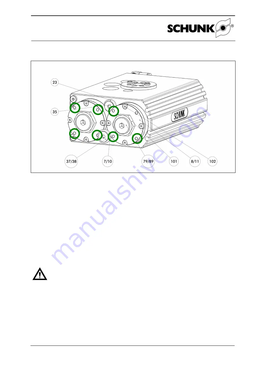
5.3 Adjusting the end positions
Figure - Adjusting the end positions
1. Loosen the screw (item 35) by approx. 1 turn using a hexagon socket screw
(SRU 20
– 40: 4, SRU 50 – 60: 5).
2. Apply pressure to air connection B. The unit swivels to stop A (basic position 0°).
3. Set the required end position by turning stop A (near the two main air connections).
Do not adjust the end stops by turning in the axial, front hexagon socket.
This could
result in the individual components becoming detached from one another. Use a face pin,
wrench which you position on the axial bores in the stop cover.
4. Purge air connection B and apply pressure to air connection A. The unit swivels to stop B
(basic position 180°).
5. Set the required end position by turning stop B (near the domed side of the SRU).
(see above point 3.
)
6. Tighten the screw (item 35) (SRU 20
– 40:10 Nm, SRU 50 – 60: 24 Nm).
7. Check that the end positions have been set correctly by swiveling the unit several times.
Warning!
The limit sleeves (item 7, 10 or 25, depending on the SRU version) limit the adjust-
ment range of the stops. For safety reasons, the unit must only be operated when the
limit sleeves are installed.


