background image

Basic safety notes

10

03.00 | SRH-plus-D | Assembly and Operating Manual | en | 1424337

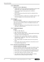
2.7 Personal protective equipment

Use of personal protective equipment

Personal protective equipment serves to protect staff against
danger which may interfere with their health or safety at work.
• When working on and with the product, observe the

occupational health and safety regulations and wear the
required personal protective equipment.

• Observe the valid safety and accident prevention regulations.
• Wear protective gloves to guard against sharp edges and

corners or rough surfaces.

• Wear heat-resistant protective gloves when handling hot

surfaces.

• Wear protective gloves and safety goggles when handling

hazardous substances.

• Wear close-fitting protective clothing and also wear long hair in

a hairnet when dealing with moving components.

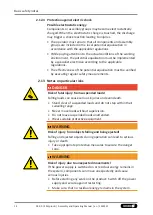
2.8 Notes on safe operation

Incorrect handling of the personnel

Incorrect handling and assembly may impair the product's safety
and cause serious injuries and considerable material damage.
• Avoid any manner of working that may interfere with the

function and operational safety of the product.

• Use the product as intended.
• Observe the safety notes and assembly instructions.
• Do not expose the product to any corrosive media. This does

not apply to products that are designed for special
environments.

• Eliminate any malfunction immediately.
• Observe the care and maintenance instructions.
• Observe the current safety, accident prevention and

environmental protection regulations regarding the product's
application field.

2.9 Transport

Handling during transport

Incorrect handling during transport may impair the product's
safety and cause serious injuries and considerable material
damage.
• When handling heavy weights, use lifting equipment to lift the

product and transport it by appropriate means.

Содержание SRH-plus-D

Страница 1: ...Translation of Original Operating Manual Assembly and Operating Manual SRH plus D Pneumatic swivel unit ...

Страница 2: ...ersion 03 00 10 01 2022 en Dear Customer thank you for trusting our products and our family owned company the leading technology supplier of robots and production machines Our team is always available to answer any questions on this product and other solutions Ask us questions and challenge us We will find a solution Best regards Your SCHUNK team Customer Management Tel 49 7133 103 2503 Fax 49 713...

Страница 3: ... Personal protective equipment 10 2 8 Notes on safe operation 10 2 9 Transport 10 2 10 Malfunctions 12 2 11 Disposal 12 2 12 Fundamental dangers 12 2 12 1 Protection during handling and assembly 12 2 12 2 Protection during commissioning and operation 13 2 12 3 Protection against dangerous movements 13 2 12 4 Protection against electric shock 14 2 13 Notes on particular risks 14 3 Technical data 16...

Страница 4: ...5 7 Maintenance 36 7 1 Notes 36 7 2 Maintenance interval 36 7 3 Lubricants Lubrication points basic lubrication 37 7 4 Inspect and set shock absorbers 37 7 4 1 Inspect shock absorbers 37 7 4 2 Set shock absorber overhang 38 7 4 3 Shock absorber types and shock absorber overlap h 38 7 5 Servicing shock absorbers absorber variant W 39 7 6 Changing shock absorbers base unit 40 7 7 Dismantling and ass...

Страница 5: ...tions the documents listed under 1 1 3 5 are applicable 1 1 1 Presentation of Warning Labels To make risks clear the following signal words and symbols are used for safety notes DANGER Danger for persons Non observance will inevitably cause irreversible injury or death WARNING Dangers for persons Non observance can lead to irreversible injury and even death CAUTION Dangers for persons Non observan...

Страница 6: ...lus D 40 SRH plus D 50 SRH plus D 60 1 1 5 Variants This operating manual applies to the following variations SRH plus D with electrical feed through EDF and lateral cable outlet 1 2 Warranty If the product is used as intended the warranty is valid for 24 months from the ex works delivery date under the following conditions Observe the specified maintenance and lubrication intervals Observe the am...

Страница 7: ... 5514998 5515002 Content of the accessories pack 7 8 42 1 4 Accessories A wide range of accessories are available for this product For information regarding which accessory articles can be used with the corresponding product variants see catalog data sheet 1 4 1 Sealing kit ID Sealing kit SRH plus D SRH plus D 20 25 30 35 40 50 60 5521800 5521802 5521804 5521806 5521808 5521810 5521812 Contents of...

Страница 8: ... with The product is intended for industrial and industry oriented use Appropriate use of the product includes compliance with all instructions in this manual 2 2 Not intended use Inappropriate use includes using the product as a cutting tool or drilling tool for example Any utilization that exceeds or differs from the appropriate use is regarded as misuse 2 3 Constructional changes Implementation...

Страница 9: ...orking with the product the personnel must have read and understood the complete assembly and operating manual Observe the national safety regulations and rules and general safety instructions The following personal qualifications are necessary for the various activities related to the product Trained electrician Due to their technical training knowledge and experience trained electricians are abl...

Страница 10: ...moving components 2 8 Notes on safe operation Incorrect handling of the personnel Incorrect handling and assembly may impair the product s safety and cause serious injuries and considerable material damage Avoid any manner of working that may interfere with the function and operational safety of the product Use the product as intended Observe the safety notes and assembly instructions Do not expos...

Страница 11: ...Basic safety notes Secure the product against falling during transportation and handling Stand clear of suspended loads 11 03 00 SRH plus D Assembly and Operating Manual en 1424337 ...

Страница 12: ... proper disposal 2 12 Fundamental dangers General Observe safety distances Never deactivate safety devices Before commissioning the product take appropriate protective measures to secure the danger zone Disconnect power sources before installation modification maintenance or calibration Ensure that no residual energy remains in the system If the energy supply is connected do not move any parts by ...

Страница 13: ...er rely solely on the response of the monitoring function to avert danger Until the installed monitors become effective it must be assumed that the drive movement is faulty with its action being dependent on the control unit and the current operating condition of the drive Perform maintenance work modifications and attachments outside the danger zone defined by the movement range To avoid accident...

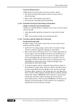
Страница 14: ...t be verified by executing regular safety measurements 2 13 Notes on particular risks DANGER Risk of fatal injury from suspended loads Falling loads can cause serious injuries and even death Stand clear of suspended loads and do not step within their swiveling range Never move loads without supervision Do not leave suspended loads unattended Wear suitable protective equipment WARNING Risk of injur...

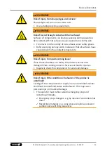
Страница 15: ...parts coming loose If the shock absorbers are faulty the product can become damaged Parts coming loose in this way can lead to injuries Regularly check the components for wear and damage WARNING Risk of injury if the condition or behavior of the product is undefined Cutting off the compressed air supply in an uncontrolled manner could lead to undefined states and behavior This may cause personal i...

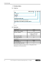
Страница 16: ...g side Mounting kit for inductive proximity switch AS Type key 3 2 Basic data Basic data swivel unit Designation Value Noise emission dB A 70 Pressure medium Compressed air compressed air quality according to ISO 8573 1 7 4 4 Min pressure bar 3 Max pressure bar 8 Basic data EDF Designation Value Max voltage V 24 Max current per wire A 1 More technical data is included in the catalog data sheet Whi...

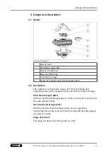
Страница 17: ...fast loading and unloading tasks with integrated fluid and electrical feed through Fluid feed through MDF With the fluid feed through gasses fluids and vacuums can be fed through without hoses Electrical feed through EDF With the electrical feed through EDF sensor signals for monitoring the product can be reliably conducted and discharged via a lateral outlet Angle of rotation The angle of rotatio...

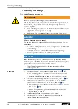
Страница 18: ...g Observe specifications in the catalog data sheet CAUTION Material damage due to opened exhaust air throttle valves If during first actuation the exhaust throttle valves are open the product may move in an uncontrolled manner Close the exhaust air throttle valves completely before applying pressure Overview 1 Screw the product to the machine system 5 2 1 20 Use centering sleeves from the enclosed...

Страница 19: ...le to the electrical feed through EDF 5 2 3 24 7 Adjust the angle of rotation 5 3 1 26 8 Adjust the swiveling speed 5 3 2 28 9 Adjust shock absorber stroke 5 3 3 29 10 Mount the sensor 5 4 32 19 03 00 SRH plus D Assembly and Operating Manual en 1424337 ...

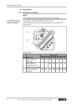
Страница 20: ... Connections on the screw on bracket The product can be assembled from two sides Centering sleeves for the mounting screws are included in the accessory kit Assembly options Item Mounting SRH plus D 20 25 30 35 40 50 60 1 Mounting screw 4 Piece M6 M6 M6 M6 M8 M10 M10 Max depth of engagement from locating surface mm 7 7 8 5 8 5 12 18 18 2 Centering sleeve 2 Piece Ø6 Ø6 Ø6 Ø6 Ø8 Ø10 Ø10 ...

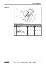
Страница 21: ...nections for attachment part Item Mounting SRH plus D 20 25 30 35 40 50 60 1 Mounting screw 4 Piece M6 M6 M6 M6 M8 M12 M12 Max depth of engagement from locating surface mm 5 5 5 5 5 5 6 8 10 5 10 5 2 Centering sleeve 2 Piece Ø6 Ø6 Ø6 Ø6 Ø8 Ø12 Ø12 21 03 00 SRH plus D Assembly and Operating Manual en 1424337 ...

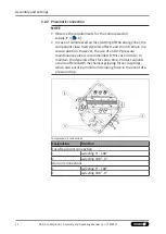
Страница 22: ...t remain in a secure position However the use of a SDV P pressure maintenance valve is recommended in this case in order to maintain the dynamic effect for some time Product variants are also offered with mechanical gripping force via springs which also ensure a minimum clamping force in the event of a pressure drop Compressed air connections Designation Function Hose free direct connection a swiv...

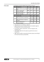
Страница 23: ... 13 G1 8 8 2 Hose connection to screw on bracket G1 8 6 5 G1 8 10 G1 8 8 3 Direct connection to screw on bracket M5 8 M5 8 M5 8 Only open the air connections required Seal those main air connections that are not needed using the locking screws from the accessory pack For hose free direct connections use the O rings from the accessory pack Use throttle valve from the accessory pack for the main air...

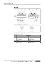
Страница 24: ...Size 20 35 SRH plus D 20 35 Sleeve 1 to 4 Connector A B Socket 1 to 4 M8 3 pin Connector A and B M12 4 pin Pin assignment Sleeve1 to 4 Connector A B Pin allocation SRH plus D 20 35 Pin Pin allocation Connector A Connector B 1 24 VDC 24 VDC 2 Socket 1 Pin 4 Socket 2 Pin 4 3 GND GND 4 Socket 4 Pin 4 Socket 3 Pin 4 ...

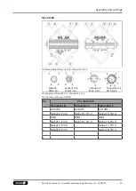
Страница 25: ...ent Sleeve 1 to 9 Connector C D E Pin allocation SRU plus D 40 60 Pin Pin allocation Connector D Connector C Connector E 1 24 VDC 24 VDC 24 VDC 2 Socket 2 Pin 4 Socket 9 Pin 2 Socket 6 Pin 4 3 GND GND GND 4 Socket 1 Pin 4 Socket 9 Pin 4 Socket 5 Pin 4 5 Socket 3 Pin 4 Socket 7 Pin 4 6 Socket 4 Pin 4 Socket 8 Pin 4 7 8 25 03 00 SRH plus D Assembly and Operating Manual en 1424337 ...

Страница 26: ...bsorber stroke Angle of rotation The angle of rotation is set in order to achieve a fine adjustment of the end positions If the end positions are adjusted the swiveling speed and absorber stroke might also have to be readjusted Swiveling speed and absorber stroke In order to ensure a smooth operating cycle for the respective operating conditions swivel speed and absorber stroke must be attuned to ...

Страница 27: ... by twisting the stop B 2 5 Check end position To do this ventilate air connection B 4 and actuate it again if necessary adjust end position 6 Tighten screw 6 7 Loosen screw 7 by approx one revolution 8 Ventilate air connection B 4 and actuate air connection A 3 9 Open the exhaust throttle valve at air connection B 4 until the swivel head 5 starts to move Swivel head swivels towards the end positi...

Страница 28: ... the shock absorber and will continue to oscillate until reaching the end position This will overload the shock absorber and may cause damage to it Adjust the swiveling speed in a way that the movement decelerate smoothly in the end position closed 1 Close both exhaust throttle valves completely 2 At air connection A 3 3 Actuate air connection A 3 4 Open the exhaust throttle valve until the swivel...

Страница 29: ...here to the maximum adjustment range Designation SRH plus D 20 25 30 35 40 50 60 Max adjustment range mm 7 5 7 5 7 5 6 5 6 5 10 5 10 5 1 Check deceleration of the movement in the end positions If the absorber stroke is too long the end position is reached too slowly If the absorber stroke is too short the assembly impacts in the end position 2 On the first shock absorber 1 remove cover 5 3 Fix bac...

Страница 30: ...op pin A 4 and tighten bolt 3 6 Fix back stop A 2 and tighten bolt 3 7 Swivel repeatedly to test the setting set again if necessary The end positions must be approached gently 8 Put on cover cap 4 9 On the second shock absorber 6 Repeat the steps for the other end position NOTE Depending on the loading condition the settings for the two shock absorbers may deviate widely from each other 5 3 4 Diag...

Страница 31: ...tion End position Target time Time T Damping Absorber stroke is too long End position is reached too slowly Movement Target position End position Target time Time T Damping Absorber stroke is too short Assembly hits the end position 31 03 00 SRH plus D Assembly and Operating Manual en 1424337 ...

Страница 32: ...rs please see catalog datasheet and 5 4 1 32 For technical data for the suitable sensors see assembly and operating manual and catalog datasheet The assembly and operating manual and catalog datasheet are included in the scope of delivery for the sensors and are available at schunk com Information on handling sensors is available at schunk com or from SCHUNK contact persons 5 4 1 Overview of senso...

Страница 33: ...o the stop in the holders 3 and clamp them in this position with screws 2 3 Make sure that screw 4 is positioned centrally under the sensor 4 Loosen screws 5 on the holder 3 Adjust the holder 3 in such a way that sensor 1 responds Re tighten screws 5 5 Swivel the product by 180 6 Adjust the holder of sensor 6 in the same way 7 Check the switching positions and test the function re adjust the posit...

Страница 34: ...ir order or dismantle product Shock absorber defective Check or if need be replace the shock absorber 7 36 6 3 Product rotates jerkily Possible cause Corrective action Too little grease in the mechanical guiding areas Clean and lubricate product 7 36 Compressed air lines blocked Check compressed air lines of damage Swiveling speed set too fast Adjust swiveling speed 5 3 2 28 6 4 Product does not m...

Страница 35: ... air can escape Check seals if necessary disassemble the product and replace seals 7 7 41 Too much grease in the mechanical movement space Clean and lubricate product 7 36 Pressure drops below minimum Check air supply 5 2 2 22 35 03 00 SRH plus D Assembly and Operating Manual en 1424337 ...

Страница 36: ...ts of SCHUNK when replacing spare and wear parts 7 2 Maintenance interval CAUTION Material damage due to hardening lubricants Lubricants harden more quickly at temperatures above 60 C leading to possible product damage Reduce the lubricant intervals accordingly Interval Mio cycles for SRH plus D 20 60 Maintenance work Daily Visually inspect the function of the shock absorbers 7 4 1 37 Interval Mio...

Страница 37: ...tective gloves Observe information on the safety data sheet of the lubricant SCHUNK recommends the lubricants listed During maintenance treat all greased areas with lubricant Thinly apply lubricant with a lint free cloth Lubricant point Lubricant The teeth and the pinion Toothgood 1 All seals Sealgood 1 7 4 Inspect and set shock absorbers 7 4 1 Inspect shock absorbers The shock absorbers are speci...

Страница 38: ...e shock absorber 2 in the piston 1 with fitting disks 5 7 4 3 38 2 After this reduce the play of the shock absorber 2 to the safety ring 3 with fitting disks 4 The shock absorber 2 must be fitted in the pistons 1 as free from play as possible 7 4 3 Shock absorber types and shock absorber overlap h Size Absorber variant Shock absorber Shock absorber overtap h mm Tolerance mm 20 W FED 14 4 6 without...

Страница 39: ...sleeve 6 and dampening ring 8 using the piston rod 3 as far as possible 8 Check the shock absorber overlap h 7 4 3 38 If necessary add or remove fitting disks on base side until the required absorber overlap h is reached 9 Remove the piston rod 3 10 Grease and insert the compression spring 5 11 Grease the piston rod 3 inside and outside and insert it 12 Mount the safety ring 4 Pay attention to the...

Страница 40: ...r 7 5 Remove safety ring 5 on piston 3 6 Pull out shock absorber 4 with fitting disks 7 Insert new shock absorbers 8 Set shock absorber overhang h 7 4 2 38 9 Set safety ring 5 in the groove of the piston 10 Turn pinion 2 to end position Piston 3 is retracted into the housing 1 11 Screw on stop cover 7 again 12 Proceed analogously for the second shock absorber 13 If necessary adjust the shock absor...

Страница 41: ...remove both stop covers 3 7 Remove curved cover 5 8 Mark the installation position of the pinion 2 19 and the pistons 24 9 Remove the protective cover 22 10 Disassemble the safety ring 49 on the pinion 2 19 11 Remove the flange 20 12 Pull the pinion 2 19 out of the housing 1 13 Assemble the swivel unit in reverse order Unless otherwise specified secure all screws and nuts with Loctite no 243 and t...

Страница 42: ...Maintenance 42 03 00 SRH plus D Assembly and Operating Manual en 1424337 7 8 Assembly drawing A 7 8 1 43 B 7 8 2 44 C 7 8 3 46 D 7 8 4 48 ...

Страница 43: ...Maintenance 7 8 1 Swivel head Swivel head 43 03 00 SRH plus D Assembly and Operating Manual en 1424337 ...

Страница 44: ...Maintenance 44 03 00 SRH plus D Assembly and Operating Manual en 1424337 7 8 2 Distributor plate EDF Size 20 35 Distributor plate with EDF 20 35 ...

Страница 45: ...Maintenance Size 40 60 Distributor plate with EDF 40 60 45 03 00 SRH plus D Assembly and Operating Manual en 1424337 ...

Страница 46: ...Maintenance 46 03 00 SRH plus D Assembly and Operating Manual en 1424337 7 8 3 Base unit 7 8 3 1 Basic components with fluid feed through Contained in seal kit Contained in accessory pack ...

Страница 47: ...tenance 7 8 3 2 Locating face end position adjustability 3 Contained in seal kit Contained in accessory pack 7 8 3 3 Piston and cover basic unit 47 03 00 SRH plus D Assembly and Operating Manual en 1424337 ...

Страница 48: ...Maintenance 48 03 00 SRH plus D Assembly and Operating Manual en 1424337 7 8 4 Screw on bracket with lateral cable outlet Size 20 35 Screw on bracket with lateral cable outlet size 20 35 ...

Страница 49: ...Maintenance Size 40 60 Screw on bracket with lateral cable outlet size 40 60 49 03 00 SRH plus D Assembly and Operating Manual en 1424337 ...

Страница 50: ... unit SRH plus D pneumatic ID number 1393104 1393112 1407400 1407403 1407404 1407405 1407409 The partly completed machine may not be put into operation until conformity of the machine into which the partly completed machine is to be installed with the provisions of the Machinery Directive 2006 42 EC is confirmed Applied harmonized standards especially EN ISO 12100 2010 Safety of machinery General ...

Страница 51: ...gration X 1 1 3 Materials and products X 1 1 4 Lighting X 1 1 5 Design of machinery to facilitate its handling X 1 1 6 Ergonomics X 1 1 7 Operating positions X 1 1 8 Seating X 1 2 Control Systems 1 2 1 Safety and reliability of control systems X 1 2 2 Control devices X 1 2 3 Starting X 1 2 4 Stopping X 1 2 4 1 Normal stop X 1 2 4 2 Operational stop X 1 2 4 3 Emergency stop X 1 2 4 4 Assembly of ma...

Страница 52: ...movable guards X 1 4 2 3 Adjustable guards restricting access X 1 4 3 Special requirements for protective devices X 1 5 Risks due to other hazards 1 5 1 Electricity supply X 1 5 2 Static electricity X 1 5 3 Energy supply other than electricity X 1 5 4 Errors of fitting X 1 5 5 Extreme temperatures X 1 5 6 Fire X 1 5 7 Explosion X 1 5 8 Noise X 1 5 9 Vibrations X 1 5 10 Radiation X 1 5 11 External ...

Страница 53: ...tuffs machinery and machinery for cosmetics or pharmaceutical products X 2 2 Portable hand held and or guided machinery X 2 2 1 Portable fixing and other impact machinery X 2 3 Machinery for working wood and material with similar physical characteristics X 3 Supplementary essential health and safety requirements to offset hazards due to the mobility of machinery X 4 Supplementary essential health ...

Страница 54: ......

Страница 55: ......

Страница 56: ... Clamping and gripping technology Bahnhofstr 106 134 D 74348 Lauffen Neckar Tel 49 7133 103 0 Fax 49 7133 103 2399 info de schunk com schunk com Folgen Sie uns I Follow us 01 2022 2022 SCHUNK GmbH Co KG 03 00 SRH plus D Assembly and Operating Manual en 1424337 ...

Отзывы: