Assembly
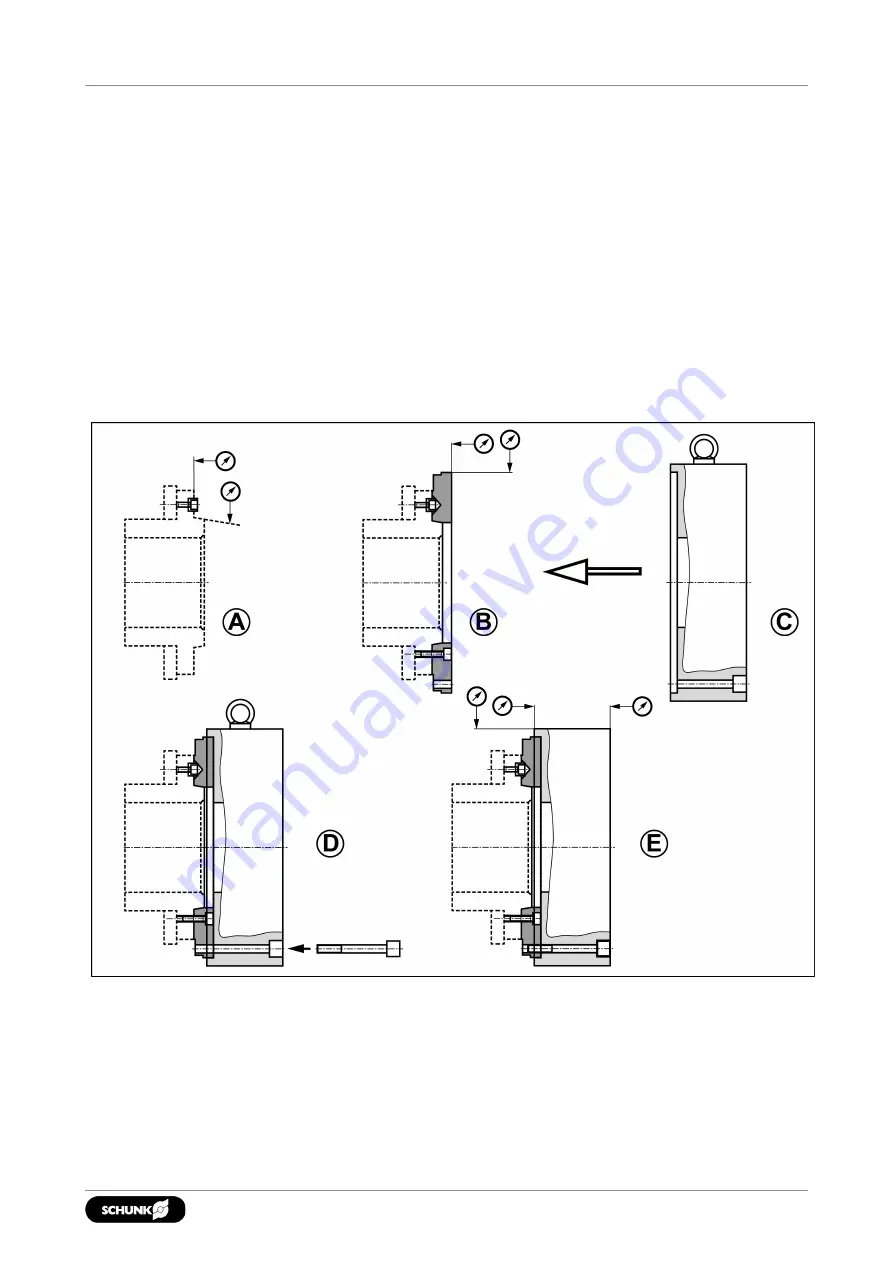
5.3 Checking the chuck mount
The machine side must be aligned prior to the flange being
installed in order to achieve high run-out accuracy of the chuck.
To do this, check the contact surfaces on the spindle for axial and
radial run-out accuracy using a dial indicator.
There should be a maximum concentricity error in the centering
of the mount of 0.01 mm and a maximum axial run-out error in
the contact surfaces of 0.01 mm. The flat surface of the spindle
must also be checked for flatness using a straight edge.
Make sure that the surface area of the flat surface is deburred at
the bore holes and is clean.
5.4 Assembly
Lathe chuck assembly
•
Chuck assembly (with cylindrical recess)
✓
Assembly preparation for the chuck with reduction or
expansion adapter plate
29
06.00 | ROTA THW3 | Power Chuck | en | 1440828
Содержание ROTA THW3
Страница 1: ...Translation of Original Operating Manual Power Chuck ROTA THW3 Assembly and Operating Manual ...
Страница 46: ...Drawing 46 06 00 ROTA THW3 Power Chuck en 1440828 9 Drawing Full chuck Accessories ...
Страница 47: ...Drawing Thrust jaw 47 06 00 ROTA THW3 Power Chuck en 1440828 ...
Страница 48: ...Drawing 48 06 00 ROTA THW3 Power Chuck en 1440828 Mount ...
Страница 49: ...Drawing Thread lock with Klemm tight 49 06 00 ROTA THW3 Power Chuck en 1440828 ...
Страница 54: ......
Страница 55: ......


