Maintenance and care
42
02.00|NSL3 turn 450-3, 450-3-Z, 570-5, 570-5-Z |en
Maintenance and care
The item numbers specified for the corresponding individual
components relate to chapter drawings.
The clamping station is designed for low-maintenance operation.
As such opening and disassembly of the clamping modules is only
necessary in exceptional cases.
The "Maintenance and care" chapter in the corresponding
assembly and operating manual applies to the NSE3 modules and
manual lathe chuck used.
At regular intervals, check that all the screw connections and
moving components of the clamping station are seated securely.
Disassembly and assembly
Replacing wearing parts (e.g. seals)
•
When removing the seals, ensure that the sealing surfaces are
not damaged.
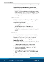
1 The ring on the base side (item 2) is used to distribute the air to
the clamping modules. To disassemble, first unscrew the
screws (item 9) and then the set-screws (item 18).
2 Alternately screw lifting screws into the threads of the set-
screws (item 18) and evenly push out the ring (item 2).
3 The set-screws (item 11 and 12) screwed into the base plate
should only be removed if required. When using again, screw in
until air-tight using a thread sealant.
4 The sealing nipples (item 14) and sealing rings (item 13) can
only be unscrewed once the threaded sleeves (item 15) have
been removed. Safety ring pliers are recommended for
removing the threaded sleeves.
5 To remove the pressure indicator, unscrew the screws (item
22) and (item 23) accessible from the base side and remove the
seal (item 24). The pressure indicator assembly group can be
disassembled further in order to change the seals.
Clean all the parts thoroughly and check for damage and wear.
Damaged, worn and lost parts must be replaced. These parts can
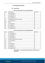
be reordered from SCHUNK in accordance with the spare parts list.
6
6.1


