background image


_________________________________________________________________________________________ 

www.schunk.de 


XND.00018.002_A – 10/2018   


31


10


 Taking out of service 

The clamping device and all accessories can be disposed of as scrap metal without any risk. 


Содержание KSC2 40

Страница 1: ..._____________________________________ www schunk de XND 00018 002_A 10 2018 1 Montage und Betriebsanleitung Installation and operating instruction Zentrischspanner Centric vice KSC2 H D SCHUNK GmbH Co Spanntechnik KG Lothringer Strasse 23 D 88512 Mengen ...

Страница 2: ... 4 Verpflichtung des Betreibers 5 2 5 Verpflichtung des Personals 6 2 6 Qualifikation des Personals 6 2 7 Persönliche Schutzausrüstung 6 2 8 Gewährleistung 6 3 Beschreibung des Spannmittels 7 3 1 Funktion 7 4 Betrieb Normalbetrieb 8 4 1 Aufspannen Ausrichten 8 4 2 Backensortiment 8 4 3 Backenwechsel 9 5 Wartung Reinigung Instandhaltung 10 5 1 Generelle Reinigung Schmierung 10 6 Fehlersuche Störung...

Страница 3: ... Bezeichnet eine mögliche gefährliche Situation Wenn die Information nicht befolgt wird können Tod oder schwerste Körperverletzungen Invalidität die Folge sein WARNUNG Bezeichnet eine möglicherweise gefährliche Situation Wenn die Information nicht befolgt wird können Sachschäden sowie leichte oder mittlere Körperverletzungen die Folgen sein Hinweis auf nützliche Tipps oder von Sachschäden HINWEIS ...

Страница 4: ...den an der Spindel Gewicht KSC2 40 mit Wendebacken 0 8 kg KSC2 65 mit Wendebacken 2 9 kg Weitere Daten siehe aktueller Katalog Schunk stationäre Spanntechnik 2 2 Vernünftigerweise vorhersehbare Fehlanwendung Eine andere als die unter Bestimmungsgemässe Verwendung festgelegte oder über diese hinausgehende Benutzung gilt als nicht bestimmungsgemäss und ist verboten Jede andere Verwendung bedarf eine...

Страница 5: ...kzeug und Werkstückteilen schützen Das Tragen einer Schutzbrille in der Nähe einer Bearbeitungsmaschine ist für Bediener und Dritte Pflicht Arbeitsweisen welche die Funktion und Betriebssicherheit des Spannmittels beeinträchtigen sind zu unterlassen 2 3 1Hinweise zur Spanntechnologie Der Bediener stellt sicher dass die Spanngeometrie und die Spannkräfte der gewählten Bearbeitungsart entsprechen Wi...

Страница 6: ...srüstung WARNUNG Augenverletzung durch fliegende heisse Späne Fliegende heisse Späne können zu schweren Augenverletzungen führen Bei sämtlichen Arbeiten an der Maschine gelten die Vorschriften der Arbeitssicherheit und Unfallverhütung Zu jeder Zeit ist eine persönliche Schutzausrüstung zu tragen insbesondere Sicherheitsschuhe Handschuhe und Schutzbrille 2 8 Gewährleistung Die Gewährleistung beträg...

Страница 7: ...en des maximalen Anzugsmomentes führen zu Schäden an der Spindel Der KSC2 kann mit wenigen Handgriffen montiert und demontiert werden 3 1 Funktion Der KSC2 ist ein Direktspanner Der mechanische Antrieb erfolgt über eine Gewindespindel Der Kraftaufbau erfolgt direkt ohne Kraftverstärker und ist linear Die Spannkräfte sind Drehmoment abhängig Beide Backen und Schieber schliessen bzw öffnen synchron ...

Страница 8: ...ie Grundkörper sind mit einer Schnittstelle ausgestattet die es ermöglicht den Spannbolzen für das Nullpunktspannsystem VERO S und den Indexierbolzen zu befestigen Achtung Der KSC2 40 hat keine Schnittstelle für das Vero S Nullpunktspannsystem Die Zyl Schraube für VERO S ist zu lang und muss auf max 42 mm gekürzt werden Der KSC 2 kann werkseitig auch mit kundenspezifischen Positionier und Befestig...

Страница 9: ...diener seite vom Grundkörper Pos 10 entfernen Zweite Spannbacke Pos 20 von der Rückseite in Richtung Bedienerseite schieben nicht vom Grundkörper entfernen Die bereits entfernte Spannbacke Pos 20 auf der Rückseite des Spanners wieder auf den Grundkörper Pos 10 schieben Spannbacken beim Montieren seitlich an das Gewindeprofil drücken und darauf achten dass alle V Nuten genutzt werden Mitnehmer Pos ...

Страница 10: ...5 1 Generelle Reinigung Schmierung Beide Spannbacken Pos 20 mittels Öffner und linksdrehen der Spindel aus dem Mitnehmer Pos 40 50 klinken Spanner soweit aufschrauben bis die Mitnehmer Pos 40 50 seitlich weg geklappt werden können Spannbacken Pos 20 vom Grundkörper entfernen Sprengring Pos 120 entfernen und nicht verlieren Spanner weiter aufschrauben bis die Gewindespindel Pos 30 durch die Fettlüc...

Страница 11: ...ontage Beide Spannbacken Pos 20 mittels Öffner und linksdrehen der Spindel aus dem Mitnehmer Pos 40 50 klinken Spanner soweit aufschrauben bis die Mitnehmer Pos 40 50 seitlich weggeklappt werden können Spannbacken Pos 20 vom Grundkörper Pos 10 entfernen Bei Bedarf den Sprengring Pos 120 entfernen und die Mitnehmer Pos 40 50 ausschrauben 120 20 40 50 20 10 30 ...

Страница 12: ...bdeckblech Pos 65 entfernen Gewindestifte Pos 100 auf beiden Seiten lösen Zylinder Schrauben M6x20 Pos 90 demontieren Zentriergabel Pos 60 entfernen und nicht verlieren Gewindespindel Pos 30 kann jetzt herausgezogen werden 7 2 2Demontage Abdeckblech Abdeckblech seitlich in eine Rundung Schieben Auf der gleichen Seite auf das Abdeckblech drücken bis sich das Blech aus der Verriegelung löst 100 60 9...

Страница 13: ...kann ob die Mitnehmer Pos 40 50 symmetrisch zum Grundkörper Pos 10 sind Im Falle dass die Mitnehmer symmetrisch sind können die Spannbacken montiert werden Im Falle dass die Mitnehmer nicht symmetrisch zum Grundkörper sind muss das Zentrum neu eingestellt werden 7 4 Zentrumseinstellung Beide Zylinder Schrauben Pos 90 mit 9Nm anziehen Seitliche Gewindestifte Pos 100 so einstellen dass die Mitnehmer...

Страница 14: ...del 1 40 CGM 065 105 11 CGM 040 105 11 Mitnehmer Bedienseite 1 50 CGM 065 106 11 CGM 040 106 11 Mitnehmer Rückseite 1 60 CGM 065 108 11 CGM 040 107 11 Zentriergabel 1 70 CGM 065 115 11 CGM 040 115 11 Abdeckblech 1 80 CGM 065 114 11 CGM 040 109 11 Spanndraht 4 90 XNN 10301 363 XNN 10301 260 Zylinder Schraube In 6kt 2 100 XNN 10706 357 XNN 10706 304 Gewindestift In 6kt 4 110 XNN 61071 410 XNN 61070 ...

Страница 15: ...t die Mitnehmer in die Spannbacke einklinken Die Demontage ist identisch zur Standard Wendebacke Beachten Sie dass für die einwandfreie Funktion der Backen ausreichend Materialquerschnitte vorhanden sind 9 1 1Ausfräsen der Spannform Die weichen Stahlbacken müssen für das Ausfräsen der Kontur im KSC2 gespannt werden Legen Sie in die geplante Backenöffnung ein Distanzstück Spannen Sie die Hauptspind...

Страница 16: ..._______________________________________________________________________ www schunk de XND 00018 002_A 10 2018 16 10 Ausserbetriebnahme Das Spannmittel und alle Zubehörteile können gefahrlos als Altmetall entsorgt werden ...

Страница 17: ...e organisation in charge 20 2 5 Operator duties 21 2 6 Operator qualification 21 2 7 Personal protective equipment 21 2 8 Warranty 21 3 Description of the clamping device 22 3 1 Function 22 4 Operation standard operation 23 4 1 Clamping aligning 23 4 2 Jaw range 23 4 3 Jaw change 24 5 Servicing cleaning maintenance 25 5 1 General cleaning lubrication 25 6 Troubleshooting eliminating faults 25 7 Re...

Страница 18: ...ermanent disability will result WARNING Indicates a potentially dangerous situation If the information is ignored it is possible that death or serious injury permanent disability will result WARNING Indicates a potentially dangerous situation If the information is ignored it is possible that material damage and light to medium injury will result Information on useful tips or for preventing materia...

Страница 19: ...lts in damage to the spindle Weight KSC2 40 with reversible jaws 0 8 kg KSC2 65 with reversible jaws 2 9 kg For further data please see the current catalogue Schunk stationary Workholding 2 2 Reasonably foreseeable misapplication Any application that is not in accordance with the Intended use or exceeds such intended use is considered not in accordance with the regulations and is forbidden Any oth...

Страница 20: ...s in the proximity of the processing machine wear protective goggles The clamping device must not be used in any way that impairs its function and operational safety 2 3 1Notes on clamping technology The operator is responsible for ensuring that the clamping geometry and clamping forces are suitable for the intended processing We recommend that clamping be carried out with a torque wrench in order...

Страница 21: ...ipment WARNING Risk of eye injury through ejected hot fragments Ejected hot fragments can lead to serious eye injury The regulations for safety at work and the prevention of accidents always have to be observed when working with the machine Personal protection equipment must be worn at all times in particular safety boots gloves and safety goggles 2 8 Warranty The warranty period is 24 months from...

Страница 22: ... the maximum torque results in damage to the spindle The KSC2 can be mounted and dismounted with just a few hand movements 3 1 Function The KSC2 is a direct clamping device The mechanical drive functions via a threaded spindle The force is generated directly in a linear manner without a force amplifier The clamping forces depend on the torque Both jaws and carriages close respectively open synchro...

Страница 23: ...m below using four M6 bolts The base plate is fitted with an interface to attaching the clamping bolt for the VERO S quick change palleting system and the indexing pin Important The KSC2 40 does not have an interface for the Vero S zero point clamping system The cylinder screw for VERO S is too long and must be shortened to max 42 mm The KSC2 can also be produced at the factory with customer speci...

Страница 24: ...tool body item 10 on the operator side Move the second clamping jaw item 20 from the rear towards the operator side do not remove from the tool body Slide the clamping jaw item 20 that has already been removed back on to the tool body item 10 at the rear of the vice When fitting the clamping jaws push them laterally against the threaded profile and ensure that all V grooves are used Fold the drive...

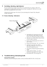
Страница 25: ... lubrication Disengage both clamping jaws item 20 from the drivers items 40 50 using the opener and turning the spindle to the left Open the vice until the drivers items 40 50 can be moved to the side Remove the clamping jaws item 20 from the tool body Remove the circlip item 120 do not lose Continue to open the vice until the threaded spindle item 30 can be seen through the greasing recess Lubric...

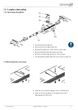
Страница 26: ...s 7 1 Removal Disengage both clamping jaws item 20 from the drivers items 40 50 using the opener and turning the spindle to the left Open the vice until the drivers items 40 50 can be moved to the side Remove the clamping jaws item 20 from the tool body item 10 Remove the circlip item 120 if necessary and turn out the drivers items 40 50 120 20 40 50 20 10 30 ...

Страница 27: ...ing see page 26 Remove the cover plate item 65 Release threaded pins item 100 on both sides Remove M6x20 cylinder screws item 90 Remove centring fork item 60 do not lose The threaded spindle item 30 can now be pulled out 7 2 2Removing the cover plate Slide the cover plate sideways into a rounded area Push on the cover plate on the same side until it disengages from the lock 100 60 90 65 30 ...

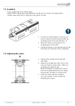
Страница 28: ...ms 40 50 are symmetrical with the tool body item 10 When the drivers are symmetrical the clamping jaws can be fitted Should the drivers not be symmetrical with the tool body the centre has to be re adjusted 7 4 Adjusting the centre Tighten both cylinder screws item 90 with 9 Nm Adjust the threaded pins item 100 on the side such that the drivers items 40 50 are symmetrical in relation to A When doi...

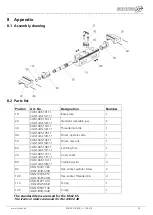
Страница 29: ...ded spindle 1 40 CGM 065 105 11 CGM 040 105 11 Driver operator side 1 50 CGM 065 106 11 CGM 040 106 11 Driver rear side 1 60 CGM 065 108 11 CGM 040 107 11 Centring fork 1 70 CGM 065 115 11 CGM 040 115 11 Cover sheet 1 80 CGM 065 114 11 CGM 040 109 11 Clamping wire 4 90 XNN 10301 363 XNN 10301 260 Hex socket cylinder screw 2 100 XNN 10706 357 XNN 10706 304 Hex socket threaded pin 4 110 XNN 61071 41...

Страница 30: ...e in the clamping jaw To disassemble the jaw proceed in the same way as with the standard reversible jaw For the proper function of the jaws it is important to ensure that the material cross sections are adequate 9 1 1Cutting out the clamping shape For cutting out the contour the soft steel jaws have to be clamped in the KSC2 Place a distance piece into the planned jaw opening Tighten the main spi...

Страница 31: ...___________________________________________________________________ www schunk de XND 00018 002_A 10 2018 31 10 Taking out of service The clamping device and all accessories can be disposed of as scrap metal without any risk ...

Страница 32: ...__________________________________________ www schunk de XND 00018 002_A 10 2018 32 H D SCHUNK GmbH Co Spanntechnik KG Lothringerstrasse 23 88512 Mengen Deutschland www schunk de Telefon 49 7572 7614 0 Fax 49 7572 7614 1099 E Mail info de schunk com ...

Отзывы: