


10
Operating instructions
Safety-monitoring module
SRB-E-204ST / SRB-E-204PE
EN
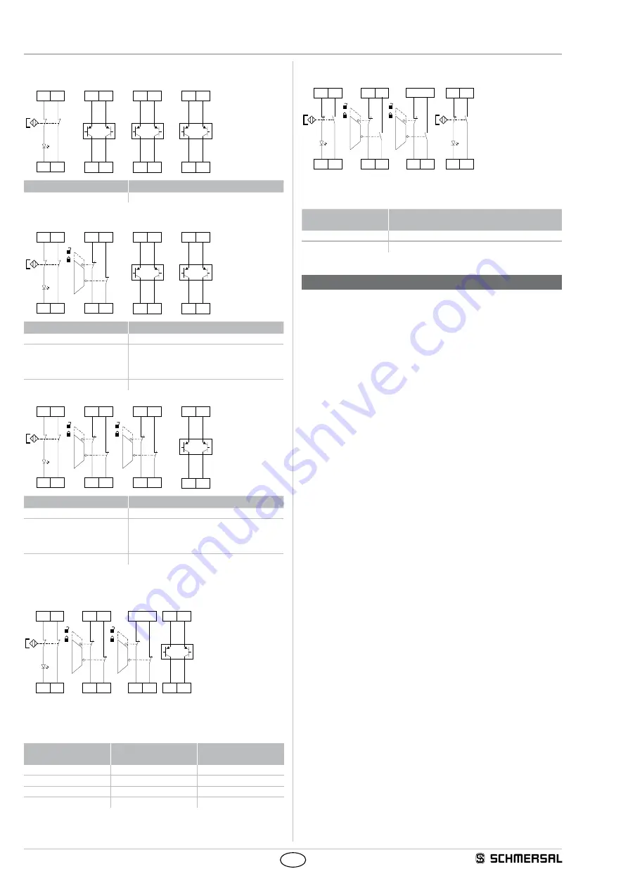
Differentiated cross-fault monitoring of sensors
(Category 4 – PL e to ISO 13849-1 possible)
S12 S22
S11 S21
S32
+24V
S42
+24V
S52
+24V
S62
+24V
S72
+24V
S82
+24V
Rotary knob position
Type / function
7
SRB-E-204PE
S12 S22
S11 S21
S32 S42
S31 S41
S52
+24V
S62
+24V
S72
+24V
S82
+24V
Rotary knob position
Type / function
8
SRB-E-204PE
11
SRB-E-204ST
Reset button with detection
of the trailing edge
12
SRB-E-204ST Autostart
S12 S22
S11 S21
S32 S42
S31 S41
S52 S62
S51 S61
S72
+24V
S82
+24V
Rotary knob position
Type / function
9
SRB-E-204PE
13
SRB-E-204ST
Reset button with detection
of the trailing edge
14
SRB-E-204ST Autostart
Without cross-wire monitoring (Sensor 1 – 4)
(Cat. 4 - PL e to ISO 13849-1 only possible with protective wiring)
S32 S42
S31 S41
S52 S62
S12 S22
S11 S21
+24
VDC
S72
+24V
S82
+24V
• Unrequired inputs S12, S22, S32, S42, S52, S62, S72, S82 must be
switched to +24VDC or bridged to outputs S11, S21, S31, S41, S51,
S61.
Rotary knob
position
Cross-wire
monitoring
Synchronisation
3
No
Yes
4
No
No
9 (SRB-E-204ST)
No
Yes
10 (SRB-E-204ST)
No
No
Dual channel signal processing NC / NO (Sensor 1 – 4)
(Category 4 – PL e to ISO 13849-1 possible)
S32 S42
S31 S41
S52 S62
S12 S22
S11 S21
+24
VDC
S72 S82
S51 S61
• Unrequired inputs S12, S32, S52, S72 must be switched to +24VDC
or bridged to outputs S11, S21, S31, S41, S51, S61.
Rotary knob
position
Function
(SRB-E-204ST)
5
Reset button (detection of the trailing edge)
6
Reset without monitoring / autostart
8. Set-up and maintenance
8.1 Commissioning
The safety relay module features protection class IP54 for installation
in a switch cabinet.
The safety relay module is delivered ready for operation.
Application 1 is preset in the factory.
8.2 Functional testing
The safety function of the safety-monitoring module must be tested.
The following conditions must be previously checked and met:
1. Correct fixing
2. Check the integrity of the cable entry and connections
3. Check the safety-monitoring module's enclosure for damage
4. Check the electrical function of the connected sensor technology
and their influence on the safety-monitoring module and the
downstream actuators
The safety relay module features self-test functions.
If a fault is detected, the system adopts a safe mode and leads,
if necessary, to undelayed deactivation of all safety outputs.
8.3 Behaviour in the case of faults
In the event of a fault the following procedure is recommended:
1. Identify faults according to flash codes from chapter 6.2.
2. Rectify the fault if it is described in the table.
3. Switch operating voltage off and on and erase fault mode.
If fault could not be rectified, please contact the manufacturer.


