schmersal SLC 420 IP 69 K Скачать руководство пользователя страница 8

8

EN

SLC 420 IP 69 K

Operating instructions

Safety light curtain

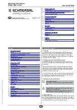
Safety distance to the hazardous area

Limit of the hazardous point

Safety distance (S)

Protection field marking

Tool - upper part

Signal to stop the  

hazardous movement
Standstill of the hazardous 

movement

t

n

 = t

B

 - t

A

Tool - lower part

t

A

S

t

B

 75 mm = max distance for protection against stepping over

To prevent persons from stepping over the protection field

this dimension must be imperatively respected and observed

The formulae and calculation examples are related to the vertical set-up 

(refer to drawing) of the light curtain with regard to the hazardous point 

Please observe the applicable harmonised EN standards and possible 

applicable national regulations

The successor standards of the EN 999 for calculating the 

minimum distances of the safety guards with regard to the 

hazardous point are EN ISO 13855 and EN ISO 13857

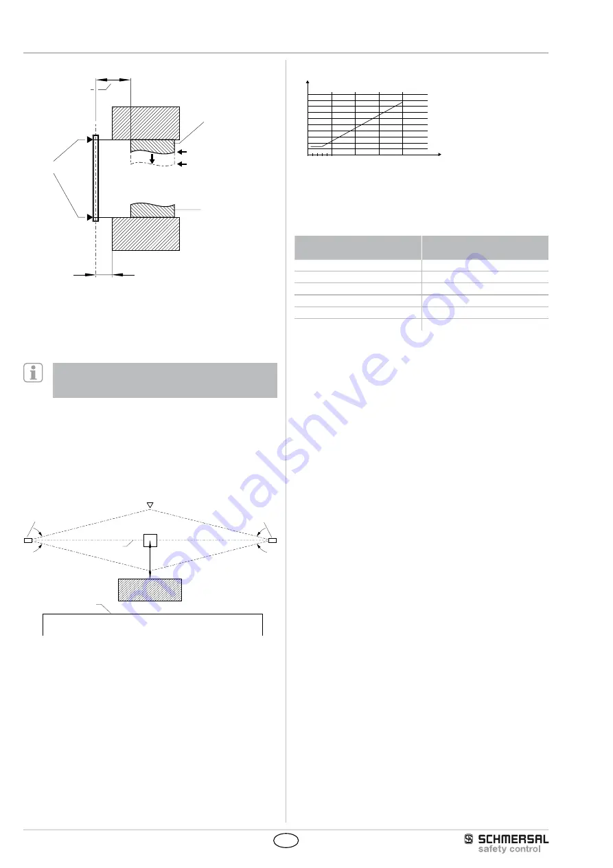
3.4.1 Minimum distance to reflecting surfaces

During the installation, the effects of reflecting surfaces must be taken 

into account In case of an incorrect installation, interruptions of the 

protection field could possibly not be detected, which could lead to 

serious injuries The hereafter-specified minimum distances with regard 

to reflecting surfaces (metal walls, floors, ceilings or parts) must be 

imperatively observed

a= 262 mm

Access direction

Receiver

Obstacle

optical axis

Transmitter

reflecting body

(eg Material container)

Limit of the hazardous 

point

a=130mm

Safety distance a

a [mm]

D [m]

0

3 5

10

100

200

300

400

500

600

700

800

900

1000

15

20

 Calculate the minimum distance to reflecting surfaces as a function of 

the distance with an aperture angles of ± 25° degrees or use the value 

from the table below

Distance between transmitter 

and receiver [m]

Minimum distance a [mm]

02 … 30

130

4

175

5

220

7

310

10

440

15

660

Formula: a = tan 2.5° x L [mm]

a = Minimum distance to reflecting surfaces

L = Distance between transmitter and receiver

Содержание SLC 420 IP 69 K

Страница 1: ...instructions are developed to execute safety related functions as part of an entire plant or machine It is the responsibility of the manufacturer of a machine or plant to ensure the correct functional...

Страница 2: ...s result ing from the use of unauthorised spare parts or accessories For safety reasons invasive work on the device as well as arbitrary re pairs conversions and modifications to the device are strict...

Страница 3: ...olution 14 mm 0 3 10 0 m resolution 30 mm Response time 1 48 L 10 ms 49 144 L 20 ms without beam coding A 1 48 L 15 ms 49 144 L 27 ms with beam coding A Rated operating voltage 24 VDC 10 PELV supply u...

Страница 4: ...as Factory setting The SLC 420 system features many functions without additional devices The following table gives an overview of the possible functions and the factory settings configuration Function...

Страница 5: ...ombination of fixed and variable blanking is possible This function allows for an interruption of the protection height without the outputs being disabled in case of material movement in the protec ti...

Страница 6: ...iver from foreign beams The beam coding A must be set for each sensor receiver and transmitter individually The function is activated by means of the NSR 0801 BUS converter and a PC or laptop If adjac...

Страница 7: ...y guard Approach speed Resolution of the safety light curtain Safety light curtain SLC 420 The safety distance for resolutions 14 mm up to 40 mm is calculated by means of the following formula 1 S 200...

Страница 8: ...13855 and EN ISO 13857 3 4 1 Minimum distance to reflecting surfaces During the installation the effects of reflecting surfaces must be taken into account In case of an incorrect installation interru...

Страница 9: ...0 587 635 671 SLC 420 E R0570 xx 69 RFB 570 667 715 751 SLC 420 E R0650 xx 69 RFB 650 747 795 831 SLC 420 E R0730 xx 69 RFB 730 827 875 911 SLC 420 E R0810 xx 69 RFB 810 907 955 991 SLC 420 E R0890 xx...

Страница 10: ...RD 24 VDC BN 0 VDC BU OSSD 1 GN OSSD 2 YE Earth connection Restart interlock manual reset bridge 1 By bridging DIAG IN pin 5 and DIAG OUT pin 6 the restart interlock manual reset is activated Protecti...

Страница 11: ...r times 6 Power OFF 7 Remove cable bridges PIN 2 3 4 and if necessary cable bridge PIN 5 6 8 Wire OSSD 1 2 pin 3 4 9 Power ON To reverse the EDM function repeat the procedure step 2 7 If the programmi...

Страница 12: ...nery parts can only be accessed by passing through the protection field of the SLC 4 The staff remains within the detection area when works are con ducted on hazardous machinery parts 5 The safety dis...

Страница 13: ...D restart continuous flashing Wiring error for function selection Restart interlock manual reset automatic mode Check connection at the receiver bridge 1 or bridge 2 must be wired refer to Wiring 1 fl...

Страница 14: ...accordance with the national prescriptions and legislations 8 Appendix 8 1 Contact Consultancy Sales K A Schmersal GmbH Industrielle Sicherheitsschaltsysteme M ddinghofe 30 D 42279 Wuppertal Tel 49 0...

Страница 15: ...rson authorized for the compilation of the technical documentation Ulrich Loss M ddinghofe 30 42279 Wuppertal Notified body for the prototype test T V Nord Cert GmbH Langemarckstr 20 45141 Essen ID n...

Страница 16: ...Safety Control GmbH Am Industriepark 33 D 84453 M hldorf Inn Telefon 49 0 86 31 187 9 60 Telefax 49 0 86 31 187 9 61 E Mail info safetycontrol com...

Отзывы: