


6
EN
SLC 420 IP 69 K
Operating instructions
Safety light curtain
2.8.5 Contactor control (EDM)
The contactor control monitors the controlled switching elements
(auxiliary contacts of the contactors) of both outputs This monitoring
is realised after each interruption of the protection field and prior to the
restart (enabling) of the outputs In this way, malfunctions of the relays
are detected, eg contact welding or contact spring breakage If the
light curtain detects a malfunctioning of the switching elements, the
outputs are locked, ie after elimination of the failure, a Power Reset is
required
The auxiliary contacts must only be connected, when the
function is activated!
After fault rectification, the operating voltage must be once switched off
and back on (power reset)
The contactor control is not activated upon delivery This
function is activated by means of the NSR-0801 BUS con-
verter and a PC or laptop
Activation of the contactor control (EDM) without software
The contactor control can be activated without PC software as of
firmware version 123, by means of cable bridges (refer to wiring
diagram)
2.8.6 Start interlock
The start interlock prevents an automatic start of the machine when the
supply voltage is switched on After enabling of the start interlock - by
the one-time interruption of the protection field -, this protective function
is deactivated until the next power reset
The start interlock is not activated upon delivery This function
is activated by means of the NSR-0801 BUS converter and a
PC or laptop
2.9 Testing
The system performs a complete self-test and safety test within 2 sec-
onds after the operating voltage has been switched on If the protection
field is not interrupted, the system switches to the ON condition In case
of an error, the outputs at the receiver do not switch to the ON state
The LED OSSD OFF starts flashing, thus emitting an error message
Further indications can be found in the chapter Fault diagnostic
During operation, the system continuously executes a self-test Safety-
relevant faults are detected within the cycle time and cause the outputs
to be switched off
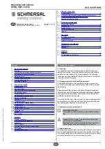
2.10 Beam coding
The beam coding of the safety light curtain must be adjusted, when
systems operating in each other's vicinity and a set-up as shown in the
image below (no interference) is impossible When supplied, the beam
coding is not active With beam coding A, a receiver can distinguish the
beams of the transmitter with the same beam coding A, which are des-
tined to this particular receiver, from foreign beams The beam coding A
must be set for each sensor (receiver and transmitter) individually The
function is activated by means of the NSR-0801 BUS converter and a
PC or laptop
If adjacent systems are operated without beam coding, the user is at
risk
no interference
E
E
R
R
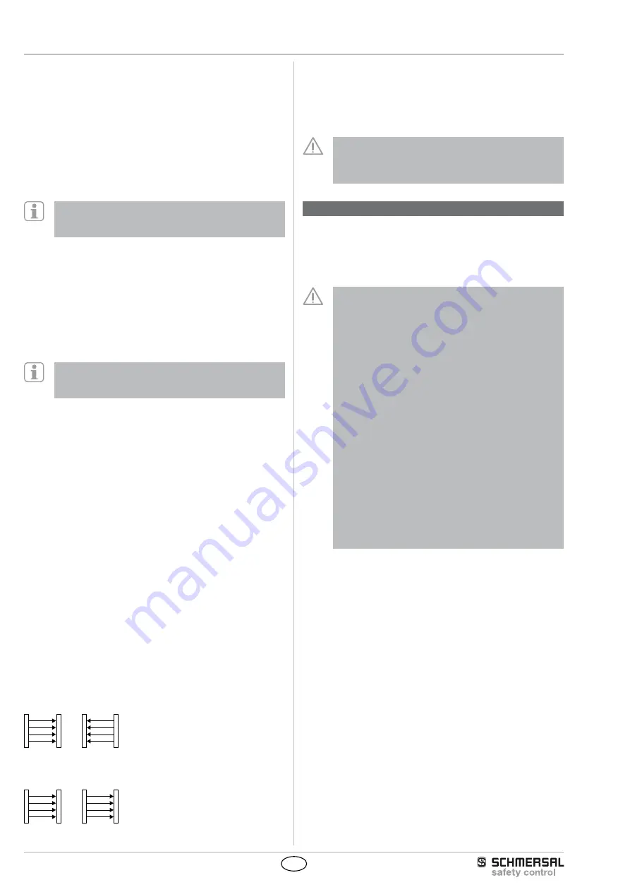
Interference: beam coding required!
E
R
R
E
• The beam coding increases the safety and avoids mutual interference
of adjacent systems
• The beam coding increases the immunity against optical interference
(eg sun light, welding sparks)
• The beam coding A is permanently shown by the transmitter and the
receiver by means of flashing LED's (refer to LED status information)
The response time of the system is increased when beam
coding A is used To this end, the safety distance must be
adjusted to the hazardous movement Refer to chapter
Response time
3. Mounting
3.1 General conditions
The following guidelines are provided as a preventative warning notice
to ensure safe and appropriate handling These guidelines are an
essential part of the safety instructions and therefore must always be
observed and respected
• The SLC must not be used on machines, which can be
stopped electrically in case of emergency
• The safety distance between the SLC and a hazardous ma-
chine movement must always be observed and respected
• Additional mechanical safety guards must be installed so
that the operator has to pass by the protection field to reach
the hazardous machine parts
• The SLC must be installed so that the personnel always
must be within the detection zone when operating the ma-
chine An incorrect installation can lead to serious injuries
• Never connect the outputs to +24VDC If the outputs are
wired to +24VDC, they are in ON state, as a result of which
they are unable to stop a hazardous situation occuring on
the application/machine
• The safety inspections must be conducted regularly
• The SLC must not be exposed to inflammable or explosive
gasses
• The connecting cables must be connected in accordance
with the installation instructions
• The fixing screws of the end caps and the mounting angle
must be firmly tightened
• When fitting the sensors, please observe that the cable
output is at the bottom in order not to affect the functionality
of the membrane
3.2 Protection field and approach
The protection field of the SLC consists of the entire range located
between the protection field markings of transmitter and receiver Ad-
ditional protective devices must ensure that the operator has to pass by
the protection field to reach the hazardous machine parts
The SLC must be installed so that personnel are always located within
the detection zone of the safety device when operating the hazardous
machine parts to be secure


