


10
EN
SLC 420 IP 69 K
Operating instructions
Safety light curtain
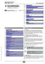
4. Electrical connection
4.1 Wiring example
5
Kn 1
Kn 2
S 1
K 1
K 2
6
1
8
2
7
3
4
Schüt
zkontr
olle/EDM
(RD)
DIAG
IN
(WH)
DIAG
IN
(GY)
DIAG
OUT
(PK)
Fr
eigabe
WA
(WH)
DIAG
OUT
(BK)
0
V
DC
(BU)
0
V
DC
(BU)
OSSD
1(
GN)
OSSD
2
(YE)
+2
4
V
DC
(BN)
+2
4
V
DC
(BN)
Brücke 1
Brücke 2
Erdung
E 1
Nur
für
Diagnose
1
2
3
4
DIAG IN (WH)
Only for Diagnostic
DIAG OUT
(BK)
+24 VDC (BN)
0 VDC (BU)
DIAG IN (GY)
DIAG OUT
(PK)
Bridge 1
Bridge 2
Release W
A (WH)
Contactor control/EDM (RD)
+24 VDC (BN)
0 VDC (BU)
OSSD 1 (GN)
OSSD 2 (YE)
Earth connection
Restart interlock (manual reset) (bridge 1)
By bridging DIAG IN (pin 5) and DIAG OUT (pin 6), the restart interlock
(manual reset) is activated
Protective mode (bridge 2)
By bridging DIAG OUT (pin 6) and authorised operation (pin 1), the
protective mode is activated
K1, K2:
Relay for processing the switching outputs OSSD 1,OSSD 2
Kn1, Kn2:
Auxiliary contacts of the last switching relay (optional) signals at input
EDM (pin 8): only to be connected when the function is activated
S1:
Command device for restart (optional)
E1:
Power supply 24 VDC ± 10%
To ensure correct functionality, an operating mode (restart
interlock or protective mode) must be selected


