schmersal SLB240 Скачать руководство пользователя страница 7

7

SLB240

Operating instructions

Safety light barriers

EN

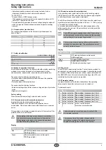
Connecting cable for emitter / receiver (4-pole)

Item N

o

Designation Description

Length

101207741 KA-0804

Female connector M12, 4-pole 5 m

101207742 KA-0805

Female connector M12, 4-pole 10 m

101207743 KA-0808

Female connector M12, 4-pole 20 m

Connecting cable for receiver (5-pole)*

Item N

o

Designation

Description

Length

101209949 A-K5P-M12-S-G-

5M-BK-2-X-A-1

Female connector M12, 
5-pole

5 m

101209948 A-K5P-M12-S-G-

15M-BK-2-X-A-1

Female connector M12, 
5-pole

15 m

* For use in the operating mode Restart Interlock (manual reset)

Adapter cable for parameter setting

Item N

o

Designation Description

Length

103013625 KA-0977

Pushbutton with  
command device
1x male connector M12, 5-pole
2x female connector M12, 5-pole

3 m

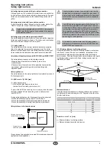
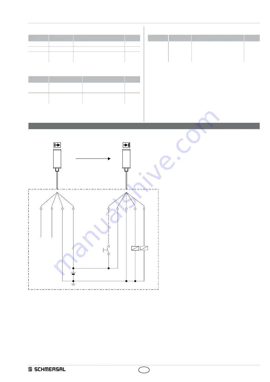
4.  Electrical connection

4.1  Wiring example SLB240

S 1

K 1

K 2

5

1

3

2

4

E 1

2

4

1

3

Not connected (BK)

Test (WH)

OSSD 2 (BK)

0 VDC (BU)

+24 VDC (BN)

Release restart (GY)

+24 VDC (BN)

0 VDC (BU)

OSSD 1 (WH)

Earth connection

Protective mode / Automatic active:

Delivery state (Command device button S1 not connected)

Restart Interlock (manual reset) active:

Refer to the chapter: operating mode activate restart interlock  

(Command device button 1 connected)

K1, K2:

Relay for processing the switching outputs 

OSSD 1,OSSD 2

S1:

Command device pushbutton for restart 

(optional)

E1:

Power supply 24 VDC ± 10%

Содержание SLB240

Страница 1: ...warning notice could lead to physical injury and or damage to the machine Content 1 About this document 1 1 Function 1 1 2 Target group authorised qualified personnel 1 1 3 Explanation of the symbols...

Страница 2: ...are strictly forbidden the manufacturer shall accept no liability for damages resulting from such invasive work arbitrary repairs conversions and or modifications to the device 2 Product description 2...

Страница 3: ...nal low Green ON state protection zone uninterrupted OSSD signal high 2 8 2 Protection mode with restart interlock In the operating mode restart interlock the safety switching outputs OSSD remain in t...

Страница 4: ...y relevant faults are detected within the reaction time and cause the outputs to be put in the OFF state and an error code is indicated 3 Mounting 3 1 General conditions The following guidelines are p...

Страница 5: ...m Prevent the possibility of reaching through between two beams Prevent the possibility of climbing through between two beams Safety distance to the hazardous area S Hazardous point Transmitter Receiv...

Страница 6: ...procal interference The response time of the system changes with the selected beam coding The safety distance must be adapted accordingly See section on reaction time When the system starts the integr...

Страница 7: ...anual reset Adapter cable for parameter setting Item No Designation Description Length 103013625 KA 0977 Pushbutton with command device 1x male connector M12 5 pole 2x female connector M12 5 pole 3 m...

Страница 8: ...achine does not exceed the response time calculated during the first putting into operation 5 The cables the connectors the caps and the mounting angles are in perfect condition 5 5 Cleaning If the op...

Страница 9: ...interlock is active SLB waiting for enabling signal Red Status of OSSD safety switch outputs is OFF protection field is not clear Red Alternating OFF pulses signalise the fault status see section on...

Страница 10: ...ompilation of the technical documentation Oliver Wacker M ddinghofe 30 42279 Wuppertal K A Schmersal GmbH Co KG M ddinghofe 30 42279 Wuppertal Deutschland Telefon 49 202 6474 0 Telefax 49 202 6474 100...

Отзывы: