Safety Field Box SFB-PN
Manual
Страница 1: ...Safety Field Box SFB PN Manual...
Страница 2: ...2 Type description Part no SFB PN IRT 8M12 IOP 103015478 Status of document Version V 1 17 Date 29 07 2019 Language EN Part no Manual 103033118...
Страница 3: ...of liability 8 2 Product description 9 2 1 Module description 9 2 1 1 Purpose ordering code module overview 9 2 1 2 Safety inputs and test pulse outputs 11 2 1 3 Safety outputs 11 2 1 4 Diagnostic in...
Страница 4: ...nnector 25 2 3 12 Optoelectronic AOPD 4 5 pole M12 connector 25 2 4 Technical Data 26 2 4 1 General technical Data 26 2 4 2 Electrical Data 27 2 5 Safety classification 28 2 5 1 Safety inputs 2 cannel...
Страница 5: ...TCI support in the TIA Portal 56 4 4 3 Parameterization without TCI support 60 5 Diagnostic system 64 5 1 PROFINET Diagnostics 64 5 1 1 Diagnostic messages Module faults 64 5 1 2 Diagnostic messages D...
Страница 6: ...l net 1 1 Enter search term SFB in the Schmersal Online Catalog at www schmersal net 1 1 3 Target group authorized qualified personnel All operations described in this manual must be carried out by tr...
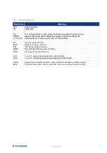
Страница 7: ...safety parameters for the validation IRT Isochronous Real Time MRP Media redundancy protocol I M Identification Maintenance SNMP Simple Network Management Protocol LLDP Link Layer Discovery Protocol 1...
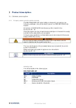
Страница 8: ...ufacturer of a machine or plant to ensure the correct functionality of the entire machine or plant The safety fieldbox must only be used according to the following versions or for applications that ar...
Страница 9: ...ions multiple fieldboxes can be connected to the power supply and field bus in series WARNING The user must evaluate and design the safety chain in accordance with the relevant standards and the requi...
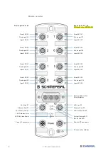
Страница 10: ...X2 Input LED X6 Error LED X1 Error LED X5 Device port X1 Device port X5 Input LED X1 Input LED X5 Error LED X0 Error LED X4 Device port X0 Device port X4 Input LED X0 Input LED X4 Rotary coding switch...
Страница 11: ...erval 500 ms 2 channel Safety switches 1oo2 with 24 V PNP solid state outputs OSSDs No cross fault monitoring of the device connection cables by the fieldbox Configurable debounce filter stable time f...
Страница 12: ...control unit referred to as the PROFINET IO Controller and connected users which are called PROFINET IO devices Communication is based on a full duplex Ethernet network running at 100 Mbit s IO contro...
Страница 13: ...ut data cyclically to the PROFIsafe slave PROFIsafe telegrams contain control and status bits The telegrams signal the states of masters slaves and initiate a status change if necessary The SFB PN saf...
Страница 14: ...erability This is done by sending cyclic test telegrams As long as the test telegrams are received again by the MRM the ring structure is intact An MRM uses this behaviour to prevent circulation of te...
Страница 15: ...ghest precision jitter 1 s Each of the individual time intervals during the IRT communication is split into an IRT interval and an open standard interval which requires the use of special IRT switches...
Страница 16: ...ing to the PROFINET specification LLDP services Link Layer Discovery Protocol The SFB PN supports the LLDP services according to the PROFINET specification Shared Device The Shared Device function is...
Страница 17: ...WARNING The default setting is used for safety switchgear with electronic OSSDs If safety switchgear with dry contacts are used cross fault monitoring must be activated WARNING For safety switchgear w...
Страница 18: ...ernally Operation of the stable time filter when using 2 channel safety inputs The stability time filter effects an intelligent discrepancy monitoring of the input signals If one contact is switched o...
Страница 19: ...ontacts Monitoring time 1 20 s 2 s for devices with OSSDs 10 s for devices with dry contacts INFORMATION For manual parameterization please ensure that the monitoring time is at least 5 times longer t...
Страница 20: ...ble time 0 1 s Safety classification Inputs X1 X2 up to Cat 4 PL e SIL 3 Output DO SCHMERSAL devices CSS range RSS range 2 3 2 Electronic safety sensor AOPD 4 5 pole M12 connector Safety sensor with e...
Страница 21: ...3 Output DO up to Cat 3 PL d SIL 2 SCHMERSAL devices MZM 100 AZM 200 AZM 201 AZM 300 2 3 4 Electronic safety interlock interlock function via 2 wires Solenoid interlock with electronic OSSD monitorin...
Страница 22: ...PL d SIL 2 SCHMERSAL devices AZM 161 FB AZM 170 FB WARNING For safety switchgear with dry contacts cross fault detection must be activated Set Stable time 0 7 s and Monitoring time 10 s 2 3 6 Electro...
Страница 23: ...h dry contacts cross fault detection must be activated Set Stable time 0 7 s and Monitoring time 10 s 2 3 8 Electromechanical safety switch 8 pole M12 connector Safety switch with dry contacts equival...
Страница 24: ...tacts cross fault detection must be activated Set Stable time 0 7 s and Monitoring time 10 s 2 3 10 Safety Relay Module SCHMERSAL SRB E Safety Relay Modules with 2 channel safety inputs monitoring 1oo...
Страница 25: ...classification Inputs X1 X2 up to Cat 4 PL e SIL 3 Output DO SCHMERSAL devices SLC 440 range SLG 440 range 2 3 12 Optoelectronic AOPD 4 5 pole M12 connector Active opto electronic protective devices A...
Страница 26: ...1 5 Nm 1 0 Nm Fixing screws Tightening torque 2x M6 max 3 0 Nm Viewing window screws Tightening torque 2x Torx 10 0 5 0 6 Nm Ambient conditions Ambient temperature 25 C 55 C Storage and transport temp...
Страница 27: ...rce C1 C2 C3 Test pulse outputs Y1 and Y2 Switching elements p type short circuit proof Rated operating voltage Ue 24 VDC Rated operating current Ie Y1 15 mA Y2 10 mA at 24 V 30 mA at GND Leakage curr...
Страница 28: ...V2 3 Conformance Class C MRP Fast Start Up V2 4 Network load class PROFINET 3 Transmission rate 100 Mbit s Full Duplex PROFINET addressing via DCP Integrated Switch Dual Port 100 Mbit s IRT capable S...
Страница 29: ...C 62061 ISO 13849 1 PL d Category 3 PFH 1 0 x 10 7 h PFDavg 8 8 x 10 3 SIL suitable for SIL 2 applications Mission time 20 years PROFINET reaction time local safety output 50 ms 2 5 4 Safety outputs 2...
Страница 30: ...omponents if applicable must be taken into consideration WARNING The maximum acceptable response times of the safety functions are defined in the risk analysis of the machine The safety field box SFB...
Страница 31: ...ist personnel can access it 3 1 1 General mounting instructions Fasten fieldbox with two M6 screws on a flat mounting surface for mechanically strain free installation The maximum tightening torque is...
Страница 32: ...3013439 7 5 VIE SS4P M12 S G 7 5M GN 2 X D 1 103013440 M12 Device connection cables 8 pole straight A coded Connecting cable male female 0 5 V SK8P M12 S G 0 5M BK 2 X A 4 69 101217786 1 0 V SK8P M12...
Страница 33: ...ion for electrical connection To supply the safety fieldbox M12 power connectors cables with a cross section of max 1 5 mm can be connected to the fieldbox CAUTION The electrical connection may only b...
Страница 34: ...X6 Input LED X2 Input LED X6 Error LED X1 Error LED X5 Device port X1 Device port X5 Input LED X1 Input LED X5 Error LED X0 Error LED X4 Device port X0 Device port X4 Input LED X0 Input LED X4 Rotary...
Страница 35: ...e ment is triggered the red LED on the device port flashes with 4 pulses After eliminating the overload at one of the device ports the fuse resets itself after a short cool down phase 3 2 4 Earth conc...
Страница 36: ...0 VDC 3 2 6 Connector Power I O Version M12 Power connector socket 4 pin T coded Pin assignment Pin Colour Signal Description of fieldbox signals 1 BN Us 24 VDC power supply SFB bridged with Pin 4 2...
Страница 37: ...test pulse outputs Check cord set and device Red flashes 4 pulses Overload device power supply Fuse device power supply has tripped check cord set and device Red flashes 5 pulses Overload digital outp...
Страница 38: ...eldbox SF green red dual LED for System Failure BF red LED for Bus Failure Err green red dual LED for fieldbox errors Pow green LED for power supply System Failure LED SF The system failure LED may ex...
Страница 39: ...d F_iPar_CRC fault Check configuration Red flashes 4 pulses Fault acknowledgement pulse length Check 500 ms pulse time for acknowledgement Red flashes 5 pulses Fault overload test pulse outputs Check...
Страница 40: ...the projected safety function is effective WARNING The safety functions configuration of the safety fieldbox and correct installation must be checked by a responsible safety specialist safety represe...
Страница 41: ...will not operate 4 2 1 Install the SFB Configuration Tool Start the installation of the SFB Configuration Tool by executing the setup file The latest version is available at www schmersal net INFORMAT...
Страница 42: ...42 4 Set up Accept the terms in the licence agreement Introduce user name and organization Select the destination folder...
Страница 43: ...4 Set up 43 Confirm and start installation Wait until the installation process is ready Finish and close the installation...
Страница 44: ...onfiguration Tool Here you can also uninstall the tool The SFB Configuration Tool is bilingual DE EN The language can be selected in the tool Detailed information can be found in the Help of the tool...
Страница 45: ...Install GSDML file of SFB PN Add the SFB PN module to the hardware configuration Configuring SFB PN in the PROFINET network IP address PROFINET name Set the F address PROFIsafe address on the field bo...
Страница 46: ...SFB Downloadable from device via the web server info page refer to Chapter 6 The import procedure for the GSDML files is described in your engineering software manual Installation of GSDML Select sou...
Страница 47: ...field devices PROFINET IO I O K A Schmersal GmbH Co KG IO Parallel SFB PN IRT 8M12 IOP With Drag Drop you can insert the SFB PN in the window Devices networks Now the SFB PN have to be connected to t...
Страница 48: ...ensure that no moisture or excessive humidity penetrates into the fieldbox CAUTION Electrostatically sensitive components Do not touch the printed circuit board directly x 100 x 10 x 1 F address 0 0...
Страница 49: ...lows To do this the PROFIsafe parameters have to be set in the engineering software Select the FS data submodule in the device overview INFORMATION For some changes of the F parameters it is necessary...
Страница 50: ...to a safe state INFORMATION Set the F_WD_Time to a value which allows toleration of communication delays In the event of erros however the response time should not be too high The minimum F watch dog...
Страница 51: ...s for the individual device ports are configured under Properties General Module parameters INFORMATION If you move the mouse over the individual parameters or fields you get a context help with an ex...
Страница 52: ...annel device Safety Inputs X1 AND X2 1 channel device Safety Input X1 0 1 2 3 4 5 6 7 Device port X0 Device port X1 Device port X2 Device port X3 Device port X4 Device port X5 Device port X6 Device po...
Страница 53: ...n 0 Qualifier Bit Device port 0 Device port passivated 1 Device port active 0 1 2 3 4 5 6 7 Device port X0 Device port X1 Device port X2 Device port X3 Device port X4 Device port X5 Device port X6 Dev...
Страница 54: ...2 3 4 5 6 7 E STOP not actuated NO contact Pos 2 NC contact Pos 2 NO contact Pos 3 NC contact Pos 3 NO contact Pos 4 Fault warning FB device Fault at FB device 1 3 n 3 FB I Response data from device...
Страница 55: ...FB 0 1 2 3 4 5 6 7 LED G24 Signal lamp red LED G24 Signal lamp green LED in push button Pos 2 LED in push button Pos 3 LED in push button Pos 4 Acknowledge device fault 1 3 n 2 FB I Request data for...
Страница 56: ...Configuration Tool If the engineering software supports TCI the settings are transferred to the SFB PN by TCI refer to chapter 4 4 2 If TCI is not supported the settings must be set manually in the SF...
Страница 57: ...nfiguration Tool automatically detects the part number of the connected field box when starting with TCI support In addition project planning data can also be entered here When saving the configuratio...
Страница 58: ...meters for each device port 1 2 With the checkbox 1 you confirm that the parameters for each device port X0 X7 have been checked Then click on Calculate CRC 2 and confirm that all parameters have been...
Страница 59: ...f the CRC values match you see the message 3 Transfer the F_iPar_CRC into the configuration of the F PLC Under Properties General PROFIsafe you can now insert the F_iPar_CRC from the clipboard in the...
Страница 60: ...box information Select the field box variant SFB PN IRT 8M12 IOP with the checkbox The corresponding part number is displayed In addition project planning data can also be entered here When saving the...
Страница 61: ...lowing steps 1 Manual input of parameters Enter the device parameters for each device port and note the dependencies be tween the parameters The optimal parameters for the different device types can b...
Страница 62: ...x you confirm that the parameters for each device port X0 X7 have been checked Then click on Calculate CRC and confirm that all parameters have been checked 3 Calculate the F_iPar_CRC The hexadecimal...
Страница 63: ...r_CRC from the clipboard in the engineering software INFORMATION For some changes of the F parameters it is necessary to enter the safety password Then the changed configuration must be Compile and Do...
Страница 64: ...h detected fault These are stored in the diagnostic buffer of the F PLC and can be analysed and visualised INFORMATION Further information can be found in the online help or in the system manual of yo...
Страница 65: ...rt X2 passivated See previous message single error at X2 1013 Device Port X3 passivated See previous message single error at X3 1014 Device Port X4 passivated See previous message single error at X4 1...
Страница 66: ...or cross fault safety inputs X4 Check parameter setting cord set and device 1025 Fault safety inputs Device Port X5 Cross fault monitoring wrong parameterized or cross fault safety inputs X5 Check pa...
Страница 67: ...s are switched off if there is a cross fault to 0 VDC INFORMATION 10 s after correcting the fault the message Fault outgoing appears and the fault can be acknowledged Error No Error message Help infor...
Страница 68: ...ON If the device port is passivated the error can no longer be detected and the message Fault outgoing appears Error No Error message Help information Note Fault Digital Output Cross fault Digital Out...
Страница 69: ...able refer to Chapter 2 2 3 This error is also reported if the safeguard has not been closed correctly or if a temporary single channel switch off has occurred INFORMATION Discrepancy errors can also...
Страница 70: ...3 6 At FB Interface communication errors the error flag COM FB Interface is set Bit 2 I ADR n 1 in submodule Functional data refer to Chapter 4 3 6 The SFB PN sends diagnostic alarms with the error n...
Страница 71: ...ally in the F_periphery block The signal ACK_REQ can be read from the F_Peripherie_DB With the input ACK_GLOB at the FB F_ACK_GL the fault can be acknowledged and the SFB PN is reintegrated The RED SF...
Страница 72: ...ther faults for the device port The error LED of the device port flashes GREEN as acknowledgement request refer to Chapter 3 3 1 Diagnostic alarm Fault outgoing is sent to the F PLC SFB PN sets the Fa...
Страница 73: ...V66 and Chrome V73 all browser versions are supported Java scripts must be enabled for correct display The web server can be started in three different ways 1 Via the engineering software of the F PLC...
Страница 74: ...on Field Box Discovery to search the SFB If you click on the IP address the SFB s web server will be started and the field box data will be displayed 3 By entering the IP address in an Internet browse...
Страница 75: ...e language of the display can be changed with the language buttons between German and English 2 Blink SFB The Blink SFB button sends a signal to a connected field box and the SF LED flashes green for...
Страница 76: ...Display when a fault was detected after power on of the field box The time starts again after each power on of the field box Status icon Fault active Fault incoming Fault fixed Fault outgoing Fault n...
Страница 77: ...Page Status Device Ports The Status Device Ports page displays the fault status and I O status of each device port The meaning of the colours of the status indicators are explained on the Help page r...
Страница 78: ...78 6 Web Server 6 1 4 Page Parameters The Parameters page displays the set parameter values from each device port If the SFB PN has not been parameterized yet the parameter values are empty...
Страница 79: ...rver 79 6 1 5 Page Help The Help page shows the meaning of the colours of all status displays on the web server In addition the limit values are displayed for the supply voltage and the field box temp...
Страница 80: ...erver 6 1 6 Page Info The Info page shows the type designation the order number and the support address of Schmersal The GSDML file saved in the field box can be downloaded using the Download GSDML Fi...
Страница 81: ...ion with shorter cable lengths small The design examples listed in the table on the next page apply to the following assumptions The examples represent maximum configurations If individual cable lengt...
Страница 82: ...Maximum 28 3 5 10 0 m 10 0 m 7 5 m AZM 300 Medium 32 4 7 5 m 7 5 m 5 0 m AZM 300 Small 40 5 7 5 m 5 m 3 5 m AZM 400 Maximum 16 2 10 0 m 10 0 m 7 5 m AZM 400 Medium 16 2 7 5 m 7 5 m 5 0 m AZM 400 Small...
Страница 83: ...ation of conformity can be downloaded from the internet at www schmersal net K A Schmersal GmbH Co KG M ddinghofe 30 D 42279 Wuppertal Postfach 24 02 63 D 42232 Wuppertal Phone 49 0 2 02 64 74 0 Telef...
Страница 84: ...hofe 30 D 42279 Wuppertal Postfach 24 02 63 D 42232 Wuppertal Telefon 49 0 2 02 64 74 0 Telefax 49 0 2 02 64 74 1 00 E Mail info schmersal com Internet http www schmersal com Technische nderungen vorb...