schmersal SFB-PN-IRT-8M12-IOP Скачать руководство пользователя страница 6

6

Operating instructions

Safety fieldbox

SFB-PN-IRT-8M12-IOP

EN

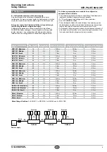
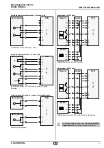
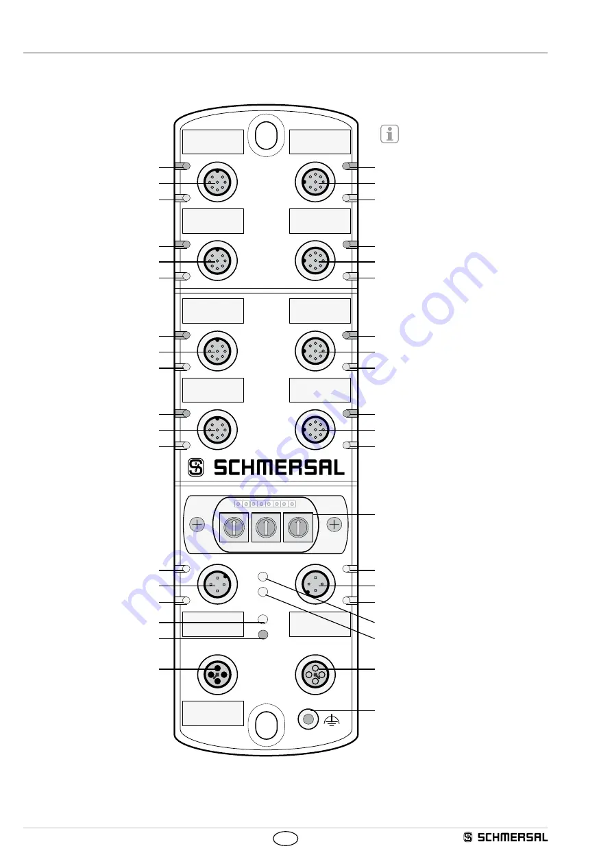
4.5  Overview of connections and LED indicators

I

E

I

E

3

2

1

0

7

6

5

4

I

E

I

E

I

E

I

E

I

E

I

E

BF

SF

Err
Pwr

A

L

A

L

P2

P1

Power

I

O

0 1

2

3

4

5

6

7

8

9

0 1

2

3

4

5

6

7

8

9

0 1

2

3

4

5

6

7

8

9

Error LED X3

Device port X3

Input LED X3

Error LED X7
Device port X7
Input LED X7

Error LED X2

Device port X2

Input LED X2

Error LED X6
Device port X6
Input LED X6

Device port X0 – X3

Device port X4 – X7

with FB interface  

for BDF200-FB

Error LED X1

Device port X1

Input LED X1

Error LED X0

Device port X0

Input LED X0

Error LED X5
Device port X5
Input LED X5

Error LED X4
Device port X4
Input LED X4

Link P1 LED

Ethernet port P1

Activity port P1 LED

Link P2 LED
Ethernet port P2
Activity port P2 LED

Fieldbox error LED

Fieldbox power LED

System fault LED
Bus fault LED

Power-IN port

Power-OUT port

FE connection, fieldbox

Rotary coding switch


Safety address

Содержание SFB-PN-IRT-8M12-IOP

Страница 1: ...rsions or for applications that are approved by the manufacturer Detailed information regarding the range of applications can be found in the chapter Product description 1 5 General safety instruction...

Страница 2: ...mation on the commissioning of the safety SFB PN fieldbox can be found on the internet at www schmersal net GSDML file for safety fieldbox SFB PN The dual language GSDML file for the SFB PN can be fou...

Страница 3: ...DO digital output should not exceed 850 mA Protection class IP67 is only reached if all M12 connectors and blanking plugs as well as the viewing window are properly fastening with screws 2 4 Safety c...

Страница 4: ...nnector 103013430 10 0 m Pre wired cable female connector 103013431 3 0 m Connecting cable male female connectors 103013432 5 0 m Connecting cable male female connectors 103013433 7 5 m Connecting cab...

Страница 5: ...3 Internal fuse elements device ports The device ports X0 X7 are designed for 0 8 A continuous current and equipped in each case with an auto resettable fuse of 1 5 A for line protection If the fuse e...

Страница 6: ...ice port X2 Input LED X2 Error LED X6 Device port X6 Input LED X6 Device port X0 X3 Device port X4 X7 with FB interface for BDF200 FB Error LED X1 Device port X1 Input LED X1 Error LED X0 Device port...

Страница 7: ...rostatically sensitive components Do not touch the printed circuit board directly When you open the inspection window ensure that no moisture or excessive humidity penetrates into the fieldbox The 3 r...

Страница 8: ...may exhibit the following display and flashing pattern LED display Description GREEN ON Field box in RUN GREEN Flashes Module fault can be acknowledged RED ON Internal field box fault RED 3 Hz F_WD_T...

Страница 9: ...igns are based on simultaneous activation of all lock and unlock functions In the event of delayed activation of the lock and unlock function larger systems are possible Device configuration version M...

Страница 10: ...00 Electromechanical interlock interlock function via 1 wire SFB X0 X7 Safety Switch 1 5 A1 DI 2 4 Y1 X1 6 7 Y2 X2 8 3 DO A2 8 3 1 5 2 4 6 7 Diag SCHMERSAL devices AZM 161 FB AZM 170 FB Electronic sen...

Страница 11: ...cibly interrupted SFB X0 X7 2 4 Y1 X1 1 2 Safety Switch Safety Switch 6 7 Y2 X2 1 2 Different safety switchgear Optoelectronic AOPD 8 pole SFB X0 X7 Receiver 1 5 A1 DI 2 4 Y1 X1 6 7 Y2 X2 8 3 DO A2 8...

Страница 12: ...land Industrie Service GmbH Alboinstr 56 12103 Berlin ID n 0035 EC prototype test certificate 01 205 5719 00 19 Person authorised for the compilation of the technical documentation Oliver Wacker M ddi...

Отзывы: