Installation manual
Page 1 of27
Installation Manual
for
PSCBR-C-100
Series PSCBR-E-133-12DI-2DIO-8RO
Страница 1: ...Installation manual Page 1 of27 Installation Manual for PSCBR C 100 Series PSCBR E 133 12DI 2DIO 8RO...
Страница 2: ...lated with greatest care and corresponds with our present status of information However we would like to point out that this document cannot always be updated at the same time as the technical further...
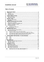
Страница 3: ...le switching relay output without testing 17 5 1 2 Single pole switching relay with external switching amplifier and testing 18 5 1 3 Dual channel switching relay output with external monitoring group...
Страница 4: ...assification as a safe function for application up to Pl e acc to EN ISO 13849 1 or SIL3 acc to EN 61508 The system software SafePLC serves the purpose of configuring and programming PSCBR C 100 modul...
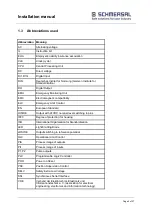
Страница 5: ...uropean Standard HISIDE Output with 24VDC nominal level switching to plus IP20 Degree of protection for housing ISO International Organisation for Standardisation LED Light Emitting Diode LOSIDE Outpu...
Страница 6: ...to the device must be checked for safe isolation from supply When installing or removing the module appropriate measures must be applied to prevent electrostatic discharge to the externally arranged...
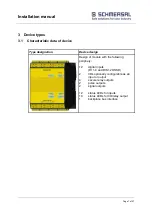
Страница 7: ...Device design Design of module with the following periphery 12 digital inputs DI 1 4 and DI8 12 OSSD 2 I Os optionally configurable as an input or output 4 secure relay outputs 2 pulse outputs 2 signa...
Страница 8: ...te is located on the left side wall of the module and contains the following information Type designation Part number Serial number Identification of hardware release Identification of software releas...
Страница 9: ...1710 1784 MHz 10V m at 1880 1960 MHz Installation in a closed housing with degree of protection IP5X or better is additionally required Safety note Electric power supply lines of the PSCBR and discont...
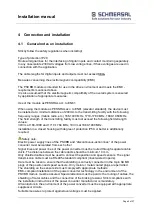
Страница 10: ...s system The PSCBR E 133 12DI 2DIO 8RO module is conneced to the PSCBR C 100 via the backplane bus Example PSCBR C 100 1 PSCBR E 133 12DI 2DIO 8RO The PSCBR E 133 12DI 2DIO 8RO module is supplied with...
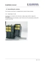
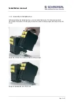
Страница 11: ...ted on C standard rails by means of snap on latches 4 4 1 Assembly on C rail The devices are inserted into the rail under an oblique angle and then snapped on downwards For disassembling use a screwdr...
Страница 12: ...ter assembling the backplane bus you can install the device For this purpose insert the module from above into the plug connection under a oblique angle and snap it onto the C rail Insert the module f...
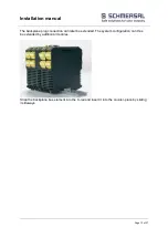
Страница 13: ...27 The backplane plug connection can later be extended The system configuration can thus be extended by additional modules Snap the backplane bus element into the C rail and insert it into the counter...
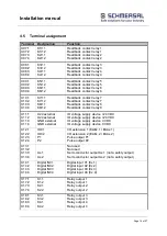
Страница 14: ...ntact relay 8 X11 1 X11 2 X11 3 X11 4 U24 external U24 external GND external GND external IO voltage supply device 24 VDC IO voltage supply device 24 VDC IO voltage supply device 0 VDC IO voltage supp...
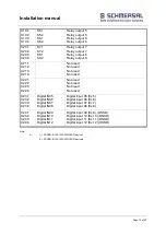
Страница 15: ...used X22 1 X22 2 X22 3 X22 4 Not used Not used Not used Not used X23 1 X23 2 X23 3 X23 4 Digital IN05 Digital IN06 Digital IN07 Digital IN08 Digital input 05 Ex 5 Digital input 06 Ex 6 Digital input 0...
Страница 16: ...s you must observe the information below in particular the specifications on wiring diagnostics The diagnostics for achieving the respective Pl and SIL in accordance with the wiring suggestions below...
Страница 17: ...onding of the internal relay or of one or more external contacts The following circuit example is only suitable for safety applications on a limited basis at a maximum Pl b according to EN 13849 1 can...
Страница 18: ...he operator recognizes the dangerous situation immediately The achievable PI mainly depends on the test rate PI d acc to EM 13849 1 can be achieved at a maximum X17 X14 K1 K2 IO01 IO02 P1 P2 X12 DI01...
Страница 19: ...ay output with external monitoring group feedback The two external monitoring contacts are switched in series supplied by clock signal P1 and read in from DI01 configured as an EMU input In the case o...
Страница 20: ...nal circuit X17 X14 K1 K2 IO01 IO02 P1 P2 X12 DI01 DI02 DI03 DI04 L L X17 1 X17 2 X17 3 X17 4 X14 1 X14 2 X14 3 X14 4 X12 1 X12 2 X12 3 X12 4 X7 K1 11 K1 12 K2 11 K2 12 X7 1 X7 2 X7 3 X7 4 P N Shut do...
Страница 21: ...EN ISO 13849 1 a sufficiently high testing rate see the remarks is required as well as PL e for the external circuit X17 X14 K1 K2 IO01 IO02 P1 P2 X12 DI01 DI02 DI03 DI04 L L X17 1 X17 2 X17 3 X17 4...
Страница 22: ...Page 22 of27 6 Configuring the PSCBR E 133 12DI 2DIO 8RO 6 1 1 Step 1 After starting the SafePLC PSCBR C 100 program you must first select the master module and then the I O extension for the PSCBR E...
Страница 23: ...on the back of the module Note The address range of the PSCBR E 133 12DI 2DIO 8RO module is from 1 15 Address 0 is reserved for the basic device 6 1 3 Step 3 In the main menu of the Safe PLC PSCBR C...
Страница 24: ...33 12DI 2DIO 8RO device x Setting the address switch of the PSCBR E 133 12DI 2DIO 8RO module Group1 EAAx 1 EAAx 6 or group1 EAAx 7 EAAx 10 When using these outputs one can choose between safety and st...
Страница 25: ...electric power supply for all the PSCBR modules and disconnect them Remove all the plug ini connections of the PSCBR E 133 12DI 2DIO 8RO module Take the module off the top hat rail make a note of the...
Страница 26: ...ent Ax 1 Ax 2 24 VDC 100 mA EAAx 1 2 24 VDC 250 mA K1 K8 24 VDC 48 VDC 230 VAC 2A 2 A 2 A 2 A Note See the PSCBR C 100 installation manual 8 3 Technical data of switching relay Switching capacity min...
Страница 27: ...ur PFH value 2 6 E 8 26 FIT per single channel output used Proof test interval EN61508 20 years after this time the module must be replaced 8 4 2 Dual channel use of the relay output according to 5 1...