


Installation manual
Page 42 of204
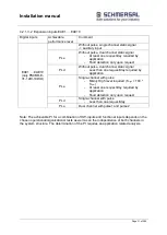
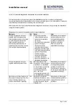
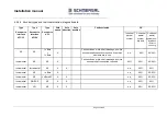
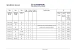
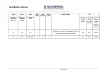
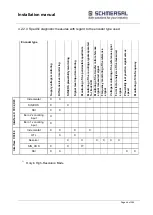
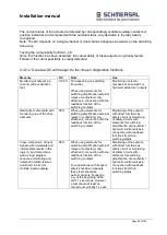
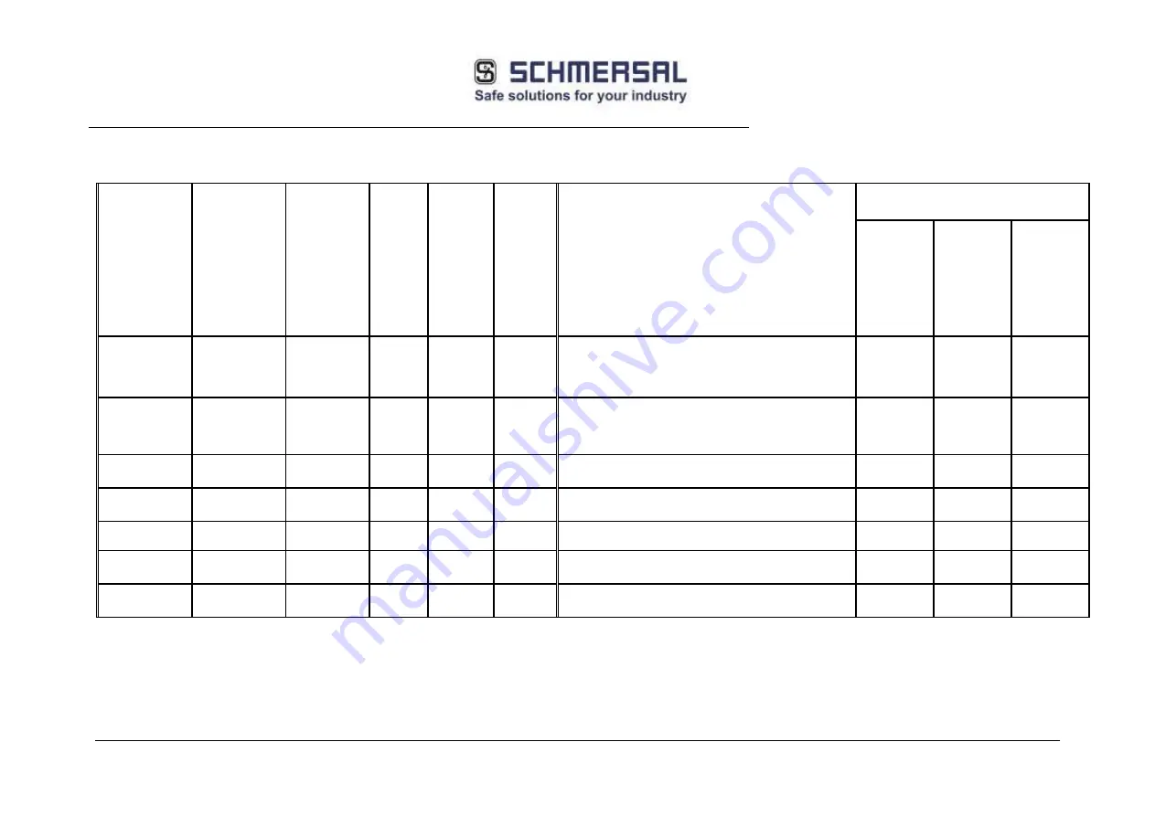
4.2.2.3 Encoder types and their combination, diagnostic data
Type
Encoder to
interface
X31/32
Type
Encoder to
interface
X31/34
Type
Encoder to
X 23
Safe
speed
Safe
direction
Safe
position
Fault exclusion
DC
1-channel
partial
system
2-channel
partial
system
dynamic
2-channel
partial
system non-
dynamic
(standstill
monitoring)
NC
NC
1 x Bero
+
1 x Bero
X
Fault exclusion mech. shaft breakage, positive
encoder shaft connection required, if common
elements are in use.
n.a.
99%
80-90%
Incremental
NC
NC
X
Fault exclusion mech. shaft breakage, positive
encoder shaft connection required
60%
99%
80-90%
Incremental
Incremental
NC
X
X
n.a.
99%
95%
Incremental
NC
1 x Bero
X
n.a.
99%
90-95%
Incremental
NC
2 x Bero 90°
X
X
n.a.
99%
90-95%
Incremental
SIN/COS
NC
X
X
n.a.
99%
99%
Incremental
HTL
NC
X
X
n.a.
99%
90-95%
Содержание PSCBR-C-10 Series
Страница 1: ...Installation manual Page 1 of204 Installation Manual For PSCBR modules Series PSCBR C 10...
Страница 178: ...Installation manual Page 178 of 204...
Страница 181: ...Installation manual Page 181 of 204 Example for a risk analysis Gefahrenanalyse Risk analysis...
Страница 200: ...Installation manual Page 200 of 204...


