background image

Annex 


Instruction Manual PROTECT-PSC 
V 2.6R01 / 04.19 


8-3 


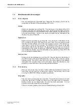
8.1.3 

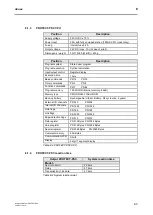
PROTECT-PSC CPU 

Position 

Description 

Supply voltage 

24 Volt DC ± 10 % 

Power input 

2.5A with fully equipped station (180mA CPU modul only) 

Fusing 

internal fuse 3.2A  

Output voltage 

24 VDC / max. 1A (in case of error!) 

Dimensions / weight 

30×110×80 (W/H/D) / 230g  


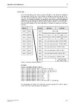
Position 

Description 

Program system 

Stored user program  

Program execution 

Cyclical calculation 

Input/output control 

Register display 

Execution time 

15ms 

Basic commands 

PS:16   

PN:16 

Timer commands 

PS:4    

PN:4 

Function commands 

PS:7    

PN:54 

Program memory  

12K WORD (internal memory: 64kB) 

Memory type 

CMOS-RAM, FLASH-ROM 

Back-up battery 

Rechargeable (Lithium Battery: life cycle max. 5 years) 

External I/O channels 

PS:240  


PN:256 

Internal I/O channels 

PS:1024    

PN:1024 

Hold flags 

PS:768 


PN:768 

Link flags 

PS:2048   

PN:2048 

Edge-detection flags 

PS:512 


PN:512 

Data register 

PS:512 Bytes  PN:1024 Bytes 

Value register 

PS:512 Bytes  PN:2048 Bytes 

Special register 

PS:2048 Bytes 

PN:2048 Bytes 

Comment memory  

64K Bytes 

Communication(PC3) 

SN-I/F 

Display 

4 digit 7 segment display 

T

T

a

a

b

b

l

l

e

e


8

8

-

-

3

3


P

P

R

R

O

O

T

T

E

E

C

C

T

T

-

-

P

P

S

S

C

C


C

C

P

P

U

U


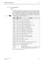
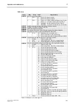
8.1.4 

PROTECT-PSC reaction time 

Output PROTECT-PSC 

System reaction time 

Mode 3 

Semi-conductor 

22.6ms 

Relay  

37.6ms 

Transmission of EL data 

47,8ms 

T

T

a

a

b

b

l

l

e

e


8

8

-

-

4

4


S

S

y

y

s

s

t

t

e

e

m

m


r

r

e

e

a

a

c

c

t

t

i

i

o

o

n

n


t

t

i

i

m

m

e

e

t

t


Содержание PROTECT-PSC

Страница 1: ...Instruction Manual PROTECT PSC V 2 6R01 04 19 Programmable Safety Controller K A Schmersal GmbH Co KG B i t t e M a k r Version V 2 6R01 04 19 Translation of the original Instruction Manual ...

Страница 2: ...translation reprint and reproduction of the document or parts thereof No part of this instruction manual may be reproduced or processed copied or disseminated using electronic systems in any form photocopy microfilm or a different procedure also not for purposes of teaching without the written consent of K A Schmersal GmbH Co KG ...

Страница 3: ... the workplace at any time Please ensure that this instruction manual is made accessible to the end users of the equipment We reserve the right to modify specifications and similar for the purpose of tech nical extension improvement We would like to point out that under provisions of the law on foreign currency and commercial transactions an export approval is to be obtained from the Japanese gove...

Страница 4: ......

Страница 5: ...2 2 Correct use 2 6 2 3 Information on basic handling 2 11 3 System description 3 1 3 1 Overview 3 3 3 2 Channel overview 3 5 3 3 ID code of the modules Module Version 3 6 3 4 PROTECT PSC operating modes 3 21 3 5 Power supply 3 23 3 6 PSC Base 3 26 3 7 PSC CPU MON PSC CPU OP MON 3 27 3 8 Input modules 3 41 3 9 Output modules 3 45 3 10 PSC SUB MON 3 48 3 11 Combined modules 3 51 3 12 Input modules ...

Страница 6: ...niert 1 13 M3 Fehler Textmarke nicht definiert 1 14 M4 Fehler Textmarke nicht definiert 1 15 M5 Fehler Textmarke nicht definiert 1 16 M6 Fehler Textmarke nicht definiert 1 17 M7 Fehler Textmarke nicht definiert 1 18 M8 Fehler Textmarke nicht definiert 1 19 O P Fehler Textmarke nicht definiert 1 20 M1 Fehler Textmarke nicht definiert 1 21 M2 Fehler Textmarke nicht definiert 1 22 M3 Fehler Textmarke...

Страница 7: ...Procedure 6 93 6 15 Changing revising 6 100 6 16 Monitoring 6 105 6 17 Documenting 6 108 6 18 Program options 6 111 6 19 CPU initialisation 6 116 6 20 Engineering Tool Version Maintenance updating 6 116 7 Operation and maintenance 7 1 7 1 Delivery status 7 2 7 2 Start up 7 2 7 3 Disturbances error messages 7 3 7 4 Maintenance 7 8 7 5 Service 7 8 8 Annex 8 1 8 1 Technical data 8 2 8 2 Considered st...

Страница 8: ......

Страница 9: ...3 1 3 1 Page lay out 1 3 1 3 2 Explanation of symbols 1 4 1 4 Product description 1 4 1 4 1 Overview of the modules 1 5 1 4 2 Brief data 1 5 1 4 3 Area of use 1 6 1 5 Mode of operation 1 6 1 5 1 Hardware 1 6 1 5 2 Software 1 6 1 6 Safety function 1 7 1 7 Performance Level 1 7 1 7 1 Risk graph 1 8 1 7 2 Determining the Performance Level 1 8 1 8 Safety Integrity Level 1 10 1 9 Calculation example 1 ...

Страница 10: ...breviations used most frequently in this doc ument are described below Module In this document a module is described as an individual physical unit which is a part of the PROTECT PSC Active module A module which is actively involved in the change of state of the PROTECT PSC corresponding to active components in electronics Assembly An assembly consists of several individual modules Channel A physi...

Страница 11: ...oc cu um me en nt t Headline The number and the name of the respective chapter are located top right and top left respectively Baseline The document name version number and creation date are located bottom left The page number within the chapter is shown bottom right Margin This area contains important information cross references to other parts of the text and bibliographic references and the inf...

Страница 12: ...d the second the page within the chapter Additional Information This symbol refers to external literature containing additional information on a par ticular theme You will find the exact title of the additional literature in the appendix Chapter 8 5 by means of the number beside the symbol 1 4 Product description The PROTECT PSC is a modular programmable safety field bus controller It serves to mo...

Страница 13: ...es of externally connected sensors actuators PSC NS IN PSC NS OUT All the above mentioned modules with the exception of the back plane have a redundant structure with two 16 bit microcontrollers monitoring each other 1 4 2 Brief data Can be used in applications up to PL e category 4 to ISO 13849 1 In operating mode 3 programming can be done by ladder diagram conform ing to IEC 61131 Programming by...

Страница 14: ...es consists of one systems A system is controlled by a microprocessor 1 5 2 Software The programmer creates the user program in the form of a ladder diagram to IEC 61131 using the PROTECT PSCsw programming software For purposes of verification the ladder diagram is converted to a statement list After having been checked by the programmer supported by the programming software the user program is tr...

Страница 15: ...PL SIL apply to a two channel safety fuction In the case of a one channel input the requirements of PL b c Category 2 as per ISO 13849 1 are only fulfilled if the safety function is marked by the change of the input from ON to OFF The minimum demand interval for a safety function of PL b c Category 2 amounts to 55 hours In the event of a safety function of PL b c Category 2 being realised a testin...

Страница 16: ... per shift 1 7 2 Determining the Performance Level In order to determine the PL for the entire system the PL for each individual element of the functional chain sensor PROTECT PSC actuator must be known The PL of the entire system can then be determined from the individual performance levels using the algorithms described below Performance Level of the PROTECT PSC The PROTECT PSC Sicherheits Klein...

Страница 17: ...e system is determined This PL PLlow is a starting point for the further determination of the overall PL Afterwards the number Nlow N of the elements is determined using PL PLlow The PL of the entire system can then be determined using these two factors and Table 1 1 PLlow Nlow PL a 3 none not permit 3 a b 2 a 2 b c 2 b 2 c d 3 c 3 d e 3 d 3 e T Ta ab bl le e 1 1 1 1 D De et te er rm mi in na at t...

Страница 18: ...failure with a function with high continuous demand rate is specified by the PFH factor average probability of a dangerous failure per hour The following is an overview of the PROTECT PSC values Safety function One two channel safety input affects one dual channel safety output Demand rate Failure probability low PFD 3 0 10 4 high continuous PFH 1 5 10 8 h Safety function Two two channel safety in...

Страница 19: ...mine the SIL the PFH or PFD factors of the chain sensor PROTECT PSC actuator must be added together depending on the operating mode The resultant SIL can be determined using the following tables PFDi SIL 10 4 bis 10 3 3 10 3 bis 10 2 2 10 2 bis 10 1 1 T Ta ab bl le e 1 1 3 3 O Op pe er ra at ti in ng g m mo od de e w wi it th h l lo ow w d de em ma an nd d r ra at te e PFHi SIL 10 8 bis 10 7 3 10 ...

Страница 20: ...ow 1 Result according to Table 1 1 PL c 1 9 2 SIL with high demand rate The SIL of the entire system is calculated as follows PFH PFHsensor PFHPROTECT PSC PFHactuator 5 2 10 6 h 1 5 10 8 h 2 6 10 8 h 5 2 10 6 h Result according to Table 1 4 SIL 1 1 9 3 SIL with low demand rate The SIL of the entire system is calculated as follows PFD PFDsensor PFDPROTECT PSC PFDactuator 4 1 10 3 3 0 10 4 1 9 10 4 ...

Страница 21: ...2 2 2 1 5 Accessibility of the programming software 2 3 2 1 6 Password protection of the programming software 2 3 2 1 7 PIN Code 2 4 2 1 8 Electrical connections 2 4 2 1 9 Shock hazard protection 2 4 2 1 10 Maintenance 2 5 2 1 11 Disposal 2 5 2 1 12 Liability 2 5 2 2 Correct use 2 6 2 2 1 Application 2 6 2 2 2 Performance Level design examinations etc 2 7 2 2 3 Use of electronic equipment for safe...

Страница 22: ...OTECT PSC 2 1 2 Danger through misuse The consequences of incorrect use may be personal injury to the user or third parties as well as damage to the controller the product or to the environment Only use the PROTECT PSC Sicherheits Kleinsteuerung for its intended purpose 2 1 3 Dangers from modification and retrofitting The PROTECT PSC Sicherheits Kleinsteuerung has been designed and constructed by ...

Страница 23: ...cians The maintenance technician is a qualified skilled worker He services the electrical and mechanical components of the controller performs maintenance work and looks for errors and eliminates them 2 1 5 Accessibility of the programming software It must be ensured that non authorized personnel have no access to the installation program of the PROTECT PSCsw programming software or may obtain suc...

Страница 24: ...ne of the following demands Safety mains transformer to IEC 61558 VDE 0570 Part 2 6 Special requirements on safety transformers for general applications IEC 61558 2 6 1997 Switch mode power supply to IEC 60950 1 Information technology equip ment Safety Part 1 and to IEC 50178 Electronic Equipment for Use in Power Installations Furthermore the power supply unit must be suitable for supplying its SE...

Страница 25: ...ed company to do so 2 1 12 Liability The contents of the following instruction manual are subject to technical modification which may arise particularly due to constant further development of the products form Schmersal Schmersal assumes no liability for any printing errors or any other inaccuracies which may be contained in this instruction manual unless these are serious faults which Schmersal d...

Страница 26: ... OFF EMERGENCY STOP command devices interlocking devices and other protective devices which protect operators from hazardous movement in the area of action of a machine Design implementation and operating errors may affect the correct operation of the PROTECT PSC system resulting in injury or damage to property or to the environment This is why only sufficiently qualified persons may operate the P...

Страница 27: ... Use of electronic equipment for safety functions This means that when using electronic equipment the so called presumed effect of harmonised standards is not completely available In Germany there should not be any problems with employer s liability insurance associations technical inspectors or technical supervisory agencies with regard to the use of electronic equipment with safety functions The...

Страница 28: ...e of safety actually achieved will therefore depend on the overall structure of this chain It is the responsibility of the user to decide which safety related measures are to be realised in the above mentioned parts of a control system The provisions laid down in the EC Machine Directive will be applicable here Any more detailed recommendations on how the safety related parts of the control system...

Страница 29: ...m to IEC 60204 1 Control functions to IEC 60204 1 Stop category to point 9 2 2 ISO 13849 1 Category Cat Performance Level PL Stop function 0 Cat 4 PLe Stop function 1 Cat 4 PLe Stop function 2 Only in connection with the input level of the PROTECT PSC system additional measures in accordance with EN 1037 protection from unexpected start up Stop function 0 Cat 4 PLe with final electrical isolation ...

Страница 30: ...tinction must be made between a stop signal of category 0 or a stop signal of category 1 Stop category 2 is not admissible for emergency actions While stop category 0 or 1 comes into question for the implementation of instructions applicable to stopping in an emergency controlling of hazarders motions cf point 9 5 4 2 instructions aimed at shutting the system down in an emergency controlling of el...

Страница 31: ...partial dependencies and non dependencies possibly under additional consideration of different operating modes etc Step 4 Assembly and wiring of the PROTECT PSC stations Step 5 Checking of correct cabling Step 6 Parameter assignment of the PROTECT PSC system Refer to chapter 6 in this respect Step 7 Reverse analysis of parameter assignment Refer to chapter 6 13 2 in this respect The reverse analys...

Страница 32: ...nstruction Manual PROTECT PSC V 2 6R01 04 19 2 12 Step 10 Documentation of steps 1 to 9 pursuant to EC Machine Directive In project documentation special reference must be made to which outputs can be used for safety functions ...

Страница 33: ... 21 3 4 3 Operating mode 1 3 21 3 4 4 Operating mode 2 3 21 3 4 5 Operating mode 3 3 21 3 5 Power supply 3 23 3 5 1 General description 3 23 3 5 2 External power supply units 3 23 3 5 3 PSC Power 3 24 3 5 4 PSC Booster 3 25 3 6 PSC Base 3 26 3 6 1 General description 3 26 3 7 PSC CPU MON PSC CPU OP MON 3 27 3 7 1 General description 3 27 3 7 2 Displays 3 30 3 7 3 Operating elements 3 31 3 7 4 Back...

Страница 34: ...C S IN LC 3 63 3 13 Relay module 3 66 3 13 1 1 13 1 General description 3 66 3 13 2 PSC S Relais 3 66 3 14 Semi conductor output module 3 69 3 14 1 General description 3 69 3 14 2 PSC S OUT 3 69 3 15 Operational input 3 72 3 15 1 General description 3 72 3 16 Operational output 3 73 3 16 1 General description 3 73 3 17 Operational input module 3 74 3 17 1 General description 3 74 3 17 2 PSC NS IN ...

Страница 35: ...C 4 semi conductor outputs 24 V DC 0 5A STOP output PSC S STP ELC 4 inputs for floating sensors 24 VDC 2 inputs for non floating sensors 24 VDC 4 semi conductor outputs 24 V DC 0 5A Input PSC S IN E 16 inputs for floating sensors 24 VDC Input PSC S IN LC 16 inputs for non floating sensors 24 VDC Relay Output PSC S Relais 2x2 relay outputs 24VDC 4 0 A Output PSC S OUT 16 semi conductor outputs 24 V...

Страница 36: ... Module type Model Marking Master module PSC CPU OP MON PSC CPU MON green Sub Master module PSC SUB MON green E A module PSC S STP E PSC S STP LC PSC S STP ELC PSC S IN E PSC S IN LC PSC S OUT PSC S Relais yellow Operational I O modules PSC NS IN PSC NS OUT gray T Ta ab bl le e 3 3 2 2 C Co ol lo ou ur r m ma ar rk ki in ng g o of f t th he e m mo od du ul le es s F Fi ig gu ur re e 3 3 1 1 B Ba a...

Страница 37: ...channel is to be understood as OR i e the CPU MON module has either 8x 1 channel OR 4x 2 channel inputs Inputs Outputs Module Opera tional Safe Opera tional Safe Semi conductor Relay 1 channel cat 2 2 channel cat 4 3 1 channel cat 2 2 channel cat 4 cat 4 PSC CPU MON PSC CPU OP MON 8 4 6 3 PSC SUB MON 8 4 6 3 PSC S STP E 6 3 4 2 PSC S STP LC 6 3 4 2 PSC S STP ELC 6 3 4 2 PSC S Relais 2x2 PSC S IN E...

Страница 38: ... S OUT 90H PSC NS IN E0H PSC NS OUT F0H T Ta ab bl le e 3 3 4 4 I ID D c co od de es s o of f t th he e m mo od du ul le es s 3 3 2 New modules version Module name Software version Hardware version PSC Power H 10 PSC Booster H 10 PSC Base H 10 PSC CPU MON 2 00 H 10 PSC CPU OP MON 2 00 H 10 PSC SUB MON 1 00 H 10 PSC S STP E 1 00 H 10 PSC S STP LC 1 00 H 10 PSC S STP ELC 1 00 H 10 PSC S Relais 1 00 ...

Страница 39: ...ystem description 3 Instruction Manual PROTECT PSC V 2 6R01 04 19 3 7 3 3 3 Module Version Confirmation 3 3 3 1POWER Module Hardware Version F Fi ig gu ur re e 3 3 2 2 P PO OW WE ER R M Mo od du ul le e ...

Страница 40: ...System description 3 Instruction Manual PROTECT PSC V 2 6R01 04 19 3 8 3 3 3 2BOOSTER Module Hardware Version Figure 3 3 BOOSTER Module ...

Страница 41: ...System description 3 Instruction Manual PROTECT PSC V 2 6R01 04 19 3 9 3 3 3 3CPU MON Module Software Version Hardware Version Figure 3 4 CPU MON Module ...

Страница 42: ...System description 3 Instruction Manual PROTECT PSC V 2 6R01 04 19 3 10 3 3 3 4CPU OP MON Module Software Version Hardware Version Figure 3 5 CPU OP MON Module ...

Страница 43: ...System description 3 Instruction Manual PROTECT PSC V 2 6R01 04 19 3 11 3 3 3 5SUB MON Module Software Version Hardware Version Figure 3 6 SUB MON Module ...

Страница 44: ...System description 3 Instruction Manual PROTECT PSC V 2 6R01 04 19 3 12 3 3 3 6S STP E Module Software Version Hardware Version Figure 3 7 S STP E Module ...

Страница 45: ...System description 3 Instruction Manual PROTECT PSC V 2 6R01 04 19 3 13 3 3 3 7S STP LC Module Software Version Hardware Version Figure 3 8 S STP LC Module ...

Страница 46: ...System description 3 Instruction Manual PROTECT PSC V 2 6R01 04 19 3 14 3 3 3 8S STP ELC Module Software Version Hardware Version Figure 3 9 S STP ELC Module ...

Страница 47: ...System description 3 Instruction Manual PROTECT PSC V 2 6R01 04 19 3 15 3 3 3 9RELAY Module Software Version Hardware Version Figure 3 10 RELAY Module ...

Страница 48: ...System description 3 Instruction Manual PROTECT PSC V 2 6R01 04 19 3 16 3 3 3 10 S IN E Module Software Version Hardware Version Figure 3 11 S IN E Module ...

Страница 49: ...System description 3 Instruction Manual PROTECT PSC V 2 6R01 04 19 3 17 3 3 3 11 S IN LC Module Software Version Hardware Version Figure 3 12 S IN LC Module ...

Страница 50: ...System description 3 Instruction Manual PROTECT PSC V 2 6R01 04 19 3 18 3 3 3 12 S OUT Module Software Version Hardware Version Figure 3 13 S OUT Module ...

Страница 51: ...System description 3 Instruction Manual PROTECT PSC V 2 6R01 04 19 3 19 3 3 3 13 NS IN Module Software Version Hardware Version Figure 3 14 NS IN Module ...

Страница 52: ...System description 3 Instruction Manual PROTECT PSC V 2 6R01 04 19 3 20 3 3 3 14 NS OUT Module Software Version Hardware Version Figure 3 15 NS OUT Module ...

Страница 53: ...r of CPU MON and CPU OP MON 3 4 4 Operating mode 2 This mode is not currently realised 3 4 5 Operating mode 3 Mode 3 is the mode for free programming It is possible to create a safe PS and an operational program PN These pro grams can be created in accordance with the user s specifications Programming is based on the ladder diagrams and function blocks in accordance with IEC 61131 Programming with...

Страница 54: ... re e 3 3 2 2 R Re el la at ti io on ns sh hi ip p b be et tw we ee en n t th he e o op pe er ra at ti in ng g m mo od de es s User program Firmware FB PIN Code 0000 Mode0 PS PN empty Default User program Firmware FB PIN Code 5678 Mode0 PS PN empty User program Firmware FB Mode 3 PS PN by user User program created by PROTECT PSCsw Entry of the PIN code by PROTECT PSCsw Delivered condition New init...

Страница 55: ...a the back plane BUS All existing and generated power voltage is monitored internally for overvoltage and undervoltage A detailed description of voltage monitoring is provided in Chap ter 3 7 5 3 5 2 External power supply units The power supply units used for power supply must comply with IEC 61000 6 2 and one of the following requirements Safety mains transformer to IEC 61558 VDE 0570 Part 2 6 Sp...

Страница 56: ...C P Po ow we er r m mo od du ul le e Housing description F Fi ig gu ur re e 3 3 3 3 P PS SC C P Po ow we er r Power LED s Green power OK Programming interface The power module has a USB interface to transfer the user program to the CPU module and to read out diagnostic information A standard USB interface must be available at the PC see Chapter 6 7 SN Interface SN I F The SN I F is used for connec...

Страница 57: ...C 10 Power input 1 0A with max number of modules Wattage max 24W Back plane bus 3 3 volt DC 10 max 15W Fusing Internal polymer fuse 1 0A Dimensions weight 30 100 80 W H D 155g T Ta ab bl le e 3 3 6 6 D Da at ta a o of f t th he e P PS SC C B Bo oo os st te er r m mo od du ul le e Housing description F Fi ig gu ur re e 3 3 4 4 P PS SC C B Bo oo os st te er r Power LED s Green power OK Polyfuse 1 0A...

Страница 58: ...always the far left module The CPU is always located to the right of it I O modules and operational I O modules can then be positioned in any order It must be considered that the operational I O modules must always be placed to the right of the safe modules If 10 or more modules including CPU are used a booster module must be posi tioned between slot 8 and slot 9 Slot 0 1 2 7 8 9 10 14 15 Module P...

Страница 59: ... PSC is in mode 3 the CPU module acts like a module with 4x2 inputs and 3x2 outputs Technical data Position Description Name PSC CPU MON PSC CPU OP MON Operating voltage current 24VDC 10 70 mA Fusing Internal fuse Inputs 3 2A Outputs 4 0A Number of safety inputs 4x2 floating Input resistence Approx 4 7 kΩ Input current 5mA High low level H 18V 3 5mA L 4 7V 0 5mA Minimum pulse duration for possible...

Страница 60: ... IN_P O P 1 O OUT_P 2 O OUT_P 3 O OUT_P 4 O OUT_P T Ta ab bl le e 3 3 1 10 0 T Te er rm mi in na al l d di ia ag gr ra am m P PS SC C C CP PU U M MO ON N P PS SC C C CP PU U O OP P M MO ON N The pin no 1 and 3 or 2 and 4 of the I P or O P connections are internally bridged in order to facilitate the connection of the power supply to the neighbouring mod ule F Fi ig gu ur re e 3 3 6 6 P PS SC C C C...

Страница 61: ...O U T 0 O U T P LM O P S Stop 1A 1 IN COM 3 IN_COM 2 S Stop 1B 4 Status displays Ready 1 OUT_COM 2 Master On 3 OUT_COM 4 S STOP input 2 S Stop 2A 1 IN COM 3 IN_COM 2 S Stop 2B 4 Start 1 IN COM 3 IN_COM 2 Reset 4 Start Reset MS1 2 RB 1 IN COM 3 IN_COM 2 MS3 4 RB 4 Read back inputs MS1 1 OUT_COM 2 MS2 3 OUT_COM 4 Semi conductor output MS3 1 OUT_COM 2 MS4 3 OUT_COM 4 Semi conductor output M1 M2 IN_P ...

Страница 62: ...s st ta at tu us s L LE ED Ds s SN I F communication LEDs The SN I F LEDs show the states of the serial reading writing line of an optionally connected gateway The PROTECT PSC interrogates this line cyclically During operation these LEDs therefore flash constantly F Fi ig gu ur re e 3 3 9 9 C Co om mm mu un ni ic ca at ti io on n L LE ED Ds s o of f t th he e P PR RO OT TE EC CT T P PS SC C C CP P...

Страница 63: ...odes are available W E the user program can be transferred Write Enable Run the user program is in operation After switching on the supply voltage the internally moves to the RUN operating mode if no errors occur during the self check The user program only starts automatically however if the RUN W E switch is similarly set to RUN R S RESTART switch The operating mode can be altered using the RUN W...

Страница 64: ...E without R S Execution of the user program is stopped Ready to transmit the configura tion user program wait for entry of the PIN code The user program is reset if the RUN W E switch is set W E during RUN The mode is shown no change from to 8 e g mode 3 The display shows the mode the examples shows mode 3 Changes to the status to transfer the configuration user program wait for entry of the PIN c...

Страница 65: ... settings the RUN W E switch must be moved to the RUN position again After this a Power OFF ON is to be executed or the R S switch ac tuated The 3 display appears on the status display for mode 3 The program is executed when an ongoing 8 is shown MODE INC buttons The internal menu structure may be navigated using these buttons The MODE button selects the individual menu options The INC button chan...

Страница 66: ... 61 Date 2 z B 2 C0 Date 3 z B 3 00 Date 4 z B 4 00 Month day z B 0922 Hour min z B 1631 CPU C102 V1 02 Slot1 z B 1104 V1 04 Slot 12 Ch z B C125 V1 25 Selected ER0 7 error information MODE CPU version Second z B 57 A Max Slot 15 Fh B MODE button pressed briefly shorter than 2s INC button pressed briefly shorter than 2s MODE button pressed for longer than 2s MODE INC button pressed for longer than ...

Страница 67: ...ver 1 year at 25 C if the PROTECT PSC is in a de energised state The battery voltage is monitored by the CPU module If the voltage drops below a minimum level a battery alarm is given error code 022 If the battery alarm continues to exist after a charging period of 8 hours the battery must be replaced F Fi ig gu ur re e 3 3 1 13 3 B Ba ac ck k u up p b ba at tt te er ry y w wi it th h c co on nn n...

Страница 68: ...the internal 3 3 volt supply is switched on and the PWR LED lights up If the external supply is switched off a controlled Power Down is performed and the PWR LED goes out 2 Brief drop in voltage 10 ms 24V 0V PWR LED External voltage Internal voltage on off on off F Fi ig gu ur re e 3 3 1 16 6 B Br ri ie ef f d dr ro op p i in n v vo ol lt ta ag ge e 1 10 0 m ms s A brief drop in voltage up to 10 m...

Страница 69: ... effective it is not possible to operate the PROTECT PSC any longer Error messages If errors occur in the above described measures or other internal external errors these are read out as error messages Every error message can be generated by processor A B Which processor has generated the message can be recognised by the prefix A B The table below shows an excerpt of the possible error messages of...

Страница 70: ...32 L Communication L000 L7FF L000 L7FF 2048 2048 L00W L7FW L00W L7FW 128 128 P Edge detection P000 P1FF P000 P1FF 512 512 P00W P1FW P00W P1FW 32 32 EL Data exchange with gateways EL000 EL3FF EL400 ELBFF 1024 2048 EL00W EL3FW EL40W ELBFW 64 128 EM Data exchange PS PN EM000 EM3FF EM400 EM7FF 1024 1024 EM00W EM3FW EM40W EM7FW 64 64 D Data register WORD D0000 0 D00FF F D0000 0 D01FF F 512 Byte 1024 By...

Страница 71: ...a memory of the gateway is faded in to the address area EL000 to ELBFF The address area EL000 to EL3FF is reserved for the PS program The address area EL400 to ELBFF is reserved for the PN program See Chapter 6 10 8 for a detailed descrip tion PS PN communication EM The address area EM000 to EM7FF is available for communication between the PS and the PN program EM000 to EM3FF is reserved for the P...

Страница 72: ... BYTE addressing is followed by an L for the low value part of the WORD and an H for the higher value part of the WORD BIT address WORD address BYTE address BIT address area Q000 LSB LSB LOW BYTE Q001 Q00W Q00L Q002 Q003 Q004 Q005 Q006 Q007 MSB Q008 LSB HIGH BYTE Q009 Q00H Q00A Q00B Q00C Q00D Q00E Q00F MSB MSB WORD address area D0000 0 LSB LSB LOW BYTE D0000 1 D0000 D0000L D0000 2 D0000 3 D0000 4 ...

Страница 73: ...e AOPDs The inputs can be parameterised by means of the programming software using one or two channels In the case of two channel use the selection can be made between an NC NC NO NO and an NO NC antivalent combination The maximum delay time between the channels in the case of two channel circuitry can be set steplessly between 0 1s and 9 9s similarly using PROTECT PSCsw In the case of PL d e Cate...

Страница 74: ... the input module used Inputs with even terminal number switch to plus by means of the sensor and with odd terminal number to minus F Fi ig gu ur re e 3 3 2 20 0 B Ba as si ic c c ci ir rc cu ui it t d di ia ag gr ra am m f fo or r i in np pu ut ts s f fo or r f fl lo oa at ti in ng g s se en ns so or rs s processor A processor A processor B input 1 COM COM channel 0 processor B channel 1 F1 F1 in...

Страница 75: ...or floating sensors The grey shaded area exists multiply depending on the input module used F Fi ig gu ur re e 3 3 2 21 1 B Ba as si ic c c ci ir rc cu ui it t d di ia ag gr ra am m i in np pu ut ts s f fo or r n no on n f fl lo oa at ti in ng g s se en ns so or rs s processor A processor A processor B input 1 channel 0 processor B channel 1 F1 F1 internal fuse 4 0A input 0 PWR 24 VDC PWR 0 VDC ...

Страница 76: ...al monitoring system for the connected 24 V DC power supply generating an error message in the case of an error Error messages If errors occur during the above described measures or other internal external errors these are read out by error messages Every error message can be generated by the A B processor The prefix A B shows the processor from which the message comes The table below provides an ...

Страница 77: ...ows the basic structure of a semi conductor output The grey shaded part of the circuit exists multiply depending on output module used Suitable protective measures e g free wheeling diode are to be taken where inductive loads are switched F Fi ig gu ur re e 3 3 2 22 2 B Ba as si ic c c ci ir rc cu ui it t d di ia ag gr ra am m f fo or r s se em mi i c co on nd du uc ct to or r o ou ut tp pu ut t m...

Страница 78: ... 23 3 B Ba as si ic c c ci ir rc cu ui it t d di ia ag gr ra am m f fo or r r re el la ay y o ou ut tp pu ut ts s The relay outputs must be opened at least once per year This can be done manually by actuating the protective device on the input side or automatically in the user program The relay outputs must be fused by means of an appropriately dimensioned fuse max 4A slow blowing processor A outp...

Страница 79: ...e connected power supply of the actuators and reads out an error message in the case of an error Error messages If errors occur during the above described measures or other internal external errors these are read out by error messages Every error message can be generated by the processor A B The prefix A B shows the processor from which the message comes The table below provides an excerpt from th...

Страница 80: ...umber of safety inputs 4x2 floating Input resistance Approx 4 7 kΩ Input current 5mA High Low level H 18V 3 5mA L 4 7V 0 5mA Minimum pulse duration for possible detection 1 4ms input filter 0 7ms Minimum pulse duration for safe detection 15ms Number of safety outputs 3x2 Output current Max 0 5 A ohmic output Maximum switching voltage 24 VDC Connection plug 36 pin plug MORIMATSU M820 09 xx 36 pin p...

Страница 81: ...9 MS3 4 RB M1 0A 1 A MS1 0A 2 OUT_COM 0B 3 B MS2 0B 4 OUT_COM M2 0C 1 C MS3 0C 2 OUT_COM 0D 3 D MS4 0D 4 OUT_COM I P 1 I IN_P 2 I IN_P 3 I IN_P 4 I IN_P O P 1 O OUT_P 2 O OUT_P 3 O OUT_P 4 O OUT_P T Ta ab bl le e 3 3 1 19 9 T Te er rm mi in na al l d de es si ig gn na at ti io on n P PS SC C S SU UB B M MO ON N The pins no 1 and 3 or 2 and 4 of the I P or O P connections are internally bridged in ...

Страница 82: ...Stop 1 1 IN COM 3 IN_COM 2 S Stop 1B 4 Status displays Ready 1 OUT_COM 2 Master On 3 OUT_COM 4 S STOP input 2 S Stop 2A 1 IN COM 3 IN_COM 2 S Stop 2B 4 Reset 1 IN COM 3 IN_COM 2 ErrorReset 4 Reset ErrorReset MS1 2 RB 1 IN COM 3 IN_COM 2 MS3 4 RB 4 Read back inputs MS1 1 OUT_COM 2 MS2 3 OUT_COM 4 Semi conductor output MS3 1 OUT_COM 2 MS4 3 OUT_COM 4 Semi conductor output M1 M2 IN_P 1 3 IN_P 2 4 OUT...

Страница 83: ...on Description Name PSC S STP E Operating voltage current 24VDC 10 70 mA Fusing Internal fuse 3 2A input circuit 4 0A output circuit Number of safety inputs 3x2 floating Input resistance Approx 4 7 kΩ Input current 5mA High Low level H 18V 3 5mA L 4 7V 0 5mA Minimum pulse duration for possible detection 1 4ms input filter 0 7ms Minimum pulse duration for safe detection 15ms Number of safety output...

Страница 84: ...T_COM M2 08 1 8 MS3 08 2 OUT_COM 09 3 9 MS4 09 4 OUT_COM I P 1 I IN_P 2 I IN_P 3 I IN_P 4 I IN_P O P 1 O OUT_P 2 O OUT_P 3 O OUT_P 4 O OUT_P T Ta ab bl le e 3 3 2 21 1 T Te er rm mi in na al l d de es si ig gn na at ti io on n P PS SC C S S S ST TP P E E The pins no 1 and 3 or 2 and 4 of the I P or O P connections are internally bridged in order to facilitate the connection of the power supply to ...

Страница 85: ... U T 1 O U T P B O U T 1 O U T P S1 S2 RB O P S Stop 1A 1 IN COM 3 IN COM 2 S Stop 1B 4 S STOP input 2 S Stop 2A 1 IN COM 3 IN COM 2 S Stop 2B 4 MS1 2 RB 1 IN COM 3 IN COM 2 MS3 4 RB 4 Read back inputs MS1 1 OUT_COM 2 MS2 3 OUT_COM 4 Semi conductor output MS3 1 OUT_COM 2 MS4 3 OUT_COM 4 Semi conductor output M1 M2 IN_P 1 3 IN_P 2 4 OUT_P 1 3 OUT_P 2 4 Power supply inputs outputs The NC con tacts o...

Страница 86: ...um pulse duration for safe detection 15ms Number of safety outputs 2x2 Output current max 0 5 A ohmic output Connection plug 28 pin plug MORIMATSU M820A 07 xx 28 pin plug EMUDEN T7509 28 xx Dimensions weight 30 x 100 x 80 mm W H D 185g T Ta ab bl le e 3 3 2 22 2 T Te ec ch hn ni ic ca al l d da at ta a P PS SC C S S S ST TP P L LC C Housing description F Fi ig gu ur re e 3 3 2 28 8 P PS SC C S S S...

Страница 87: ...MS2 RB M1 06 1 6 MS1 06 2 OUT_COM 07 3 7 MS2 07 4 OUT_COM M2 08 1 8 MS3 08 2 OUT_COM 09 3 9 MS4 09 4 OUT_COM I P 1 I IN_P 2 I IN_P 3 I IN_P 4 I IN_P O P 1 O OUT_P 2 O OUT_P 3 O OUT_P 4 O OUT_P T Ta ab bl le e 3 3 2 23 3 T Te er rm mi in na al l d de es si ig gn na at ti io on n P PS SC C S S S ST TP P L LC C The pins no 1 and 3 or 2 and 4 of the I P or O P connections are internally bridged in ord...

Страница 88: ... MS2 RB 4 Read back inputs MS3 1 OUT_COM 2 MS4 3 OUT_COM 4 Semi conductor output MS1 1 OUT_COM 2 MS2 3 OUT_COM 4 Semi conductor output M1 M2 IN_P 1 3 IN_P 2 4 OUT_P 1 3 OUT_P 2 4 Power supply inputs outputs AOPD 2 B I N 1 A I N 1 24V 0V AOPD 1 24V 24V 0V L1 AOPD 1A 1 AOPD 1B 3 L2 AOPD 2A 1 AOPD 2B 3 The NC con tacts of the actors con trolled by the corresponding semi conductor out put are read bac...

Страница 89: ... Minimum pulse duration for safe detection 15ms Number of safety outputs 2x2 Output current Max 0 5 A ohmic output Connection plug 28 pin plug MORIMATSU M820A 07 xx 28 pin plug EMUDEN T7509 28 xx Dimensions weight 30 x 100 x 80 mm W H D 185g T Ta ab bl le e 3 3 2 24 4 T Te ec ch hn ni ic ca al l d da at ta a P PS SC C S S S ST TP P E EL LC C Housing description F Fi ig gu ur re e 3 3 3 30 0 P PS S...

Страница 90: ..._COM 05 4 5 MS2 RB M1 06 1 6 MS1 06 2 OUT_COM 07 3 7 MS2 07 4 OUT_COM M2 08 1 8 MS3 08 2 OUT_COM 09 3 9 MS4 09 4 OUT_COM I P 1 I IN_P 2 I IN_P 3 I IN_P 4 I IN_P O P 1 O OUT_P 2 O OUT_P 3 O OUT_P 4 O OUT_P T Ta ab bl le e 3 3 2 25 5 T Te er rm mi in na al l d de es si ig gn na at ti io on n P PS SC C S S S ST TP P E EL LC C The pins no 1 and 3 or 2 and 4 of the I P or O P connections are internally...

Страница 91: ... 1B 2 IN COM 4 I P The NC contacts of the actors con trolled by the cor responding semi conductor output are read back here The power sup ply of the inputs must have the same potential as the power supply of the AOPDs A O U T 1 O U T P B O U T 1 O U T P RB O P MS1 2 RB 1 IN COM 3 IN COM 2 MS3 4 RB 4 Read back inputs MS1 1 OUT_COM 2 MS2 3 OUT_COM 4 Semi conductor output MS3 1 OUT_COM 2 MS4 3 OUT_CO...

Страница 92: ...l data Position Description Name PSC S IN E Operating voltage current 24VDC 10 62 mA Fusing Internal fuse 3 2A Number of safety inputs 8x2 floating Input resistance Approx 4 7 kΩ Input current 5mA High Low level H 18V 3 5mA L 4 7V 0 5mA Minimum pulse duration for possible detection 1 4ms input filter 0 7ms Minimum pulse duration for safe detection 15ms Connection plug 36 pin plug MORIMATSU M820A 0...

Страница 93: ...5B S6 0A 1 A S Stop 6A 0B 2 IN_COM 0A 3 IN_COM 0B 4 B S Stop 6B S7 0C 1 C S Stop 7A 0D 2 IN_COM 0C 3 IN_COM 0D 4 D S Stop 7B S8 0E 1 E S Stop 8A 0F 2 IN_COM 0E 3 IN_COM 0F 4 F S Stop 8B I P 1 I IN_P 2 I IN_P 3 I IN_P 4 I IN_P T Ta ab bl le e 3 3 2 27 7 T Te er rm mi in na al l d de es si ig gn na at ti io on n P PS SC C S S I IN N E E The pins no 1 and 3 or 2 and 4 of the I P connections are inter...

Страница 94: ...op 2B 4 I P IN_P 1 3 IN_P 2 4 Power supply inputs C O M B I N 1 A I N 1 C O M S3 S STOP input 3 S Stop 3A 1 IN COM 3 IN COM 2 S Stop 3B 4 C O M B I N 1 A I N 1 C O M S4 S STOP input 4 S Stop 4A 1 IN COM 3 IN COM 2 S Stop 4B 4 C O M B I N 1 A I N 1 C O M S5 S STOP input 5 S Stop 5A 1 IN COM 3 IN COM 2 S Stop 5B 4 C O M B I N 1 A I N 1 C O M S6 S STOP input 6 S Stop 6A 1 IN COM 3 IN COM 2 S Stop 6B ...

Страница 95: ...t filter 0 7ms Minimum pulse duration for safe detection 15ms Connection plug 36 pin plug MORIMATSU M820A 09 xx 36 pin plug EMUDEN T7509 36 xx Dimensions weight 30 x 100 x 80 mm W H D 190g T Ta ab bl le e 3 3 2 28 8 T Te ec ch hn ni ic ca al l d da at ta a P PS SC C S S I IN N L LC C Housing description F Fi ig gu ur re e 3 3 3 34 4 P PS SC C S S I IN N L LC C StatusLED ERR on error alarm off oper...

Страница 96: ... 4A 2 07 3 7 AOPD 4B 4 L5 08 1 8 AOPD 5A 2 09 3 9 AOPD 5B 4 L6 0A 1 A AOPD 6A 2 0B 3 B AOPD 6B 4 L7 0C 1 C AOPD 7A 2 0D 3 D AOPD 7B 4 L8 0E 1 E AOPD 8A 2 0F 3 F AOPD 8B 4 I P 1 I IN_P 2 I IN_P 3 I IN_P 4 I IN_P T Ta ab bl le e 3 3 2 29 9 T Te er rm mi in na al l d de es si ig gn na at ti io on n P PS SC C S S I IN N L LC C The pins no 1 and 3 or 2 and 4 of the I P connections are internally bridge...

Страница 97: ...V L1 AOPD 1A 1 AOPD 1B 3 AOPD 2 B I N 1 A I N 1 24 V 0V L2 AOPD 2A 1 AOPD 2B 3 AOPD 3 B I N 1 A I N 1 24 V 0V L3 AOPD 3A 1 AOPD 3B 3 AOPD 4 B I N 1 A I N 1 24 V 0V L4 AOPD 4A 1 AOPD 4B 3 AOPD 5 B I N 1 A I N 1 24 V 0V L5 AOPD 5A 1 AOPD 5B 3 AOPD 6 B I N 1 A I N 1 24 V 0V L6 AOPD 6A 1 AOPD 6B 3 AOPD 7 B I N 1 A I N 1 24 V 0V L7 AOPD 7A 1 AOPD 7B 3 AOPD 8 B I N 1 A I N 1 24 V 0V L8 AOPD 8A 1 AOPD 8B...

Страница 98: ...n the user program The relay outputs must be fused by means of an appropriately dimensioned fuse max 4A slow blowing 3 13 2 PSC S Relais Technical data Position Description Name PSC S Relais Operating voltage current 24VDC 10 107mA Number of safety outputs 2x2 floating relay outputs Output current max 4A ohmic output External fuse max 4A slow blowing Switching voltage 24 VDC Connection plug 8 Pin ...

Страница 99: ...s of relay Terminal 00h 03h connection actuator Housing description F Fi ig gu ur re e 3 3 3 36 6 P PS SC C S S R Re el la ai is s I O Address Pin no Print name Terminal name 00 01 1 0 1 1 RELAY OUT 1 2 0 1 2 3 0 1 3 RELAY OUT 2 4 0 1 4 02 03 5 2 3 1 RELAY OUT 3 6 2 3 2 7 2 3 3 RELAY OUT 4 8 2 3 4 T Ta ab bl le e 3 3 3 31 1 T Te er rm mi in na al l d de es si ig gn na at ti io on n P PS SC C S S R...

Страница 100: ...g gu ur re e 3 3 3 37 7 P PS SC C S S R Re el la ai is s t te er rm mi in na al l d di ia ag gr ra am m MS1 Enable relay I O circuit MS2 Enable relay MS1 MS2 A A B B V1 V2 MS3 Enable relay MS4 Enable relay MS3 MS4 A A B B V3 V4 0 1 1 0 1 3 0 1 4 2 3 1 2 3 2 2 3 3 2 3 4 SN I F pro toc ole pin No 0 1 1 0 1 2 0 1 3 0 1 4 2 3 1 2 3 2 2 3 3 2 3 4 ...

Страница 101: ...cts like a module with 8x2 inputs 3 14 2 PSC S OUT Technical data Position Description Name PSC S OUT Operating voltage current 24VDC 10 74mA Fusing Internal fuse 4 X 4 0A Number of safety outputs 8x2 Output current Max 0 3A ohmic load Switching voltage 24 V DC Connection plug 36 pin plug MORIMATSU M820A 09 xx 36 pin plug EMUDEN T7509 36 xx D Di im me en ns si io on ns s w we ei ig gh ht t 4 45 5 ...

Страница 102: ...7 MS8 07 4 OUT_COM M5 08 1 8 MS9 08 2 OUT_COM 09 3 9 MS10 09 4 OUT_COM M6 0A 1 A MS11 0A 2 OUT_COM 0B 3 B MS12 0B 4 OUT_COM M7 0C 1 C MS13 0C 2 OUT_COM 0D 3 D MS14 0D 4 OUT_COM M8 0E 1 E MS15 0E 2 OUT_COM 0F 3 F MS16 0F 4 OUT_COM O P 1 O OUT_P 2 O OUT_P 3 O OUT_P 4 O OUT_P T Ta ab bl le e 3 3 3 33 3 T Te er rm mi in na al l d de es si ig gn na at ti io on n P PS SC C S S O OU UT T The pins no 1 an...

Страница 103: ...2 MS4 3 OUT_COM 4 Semi conductor output M2 MS3 MS4 MS5 1 OUT_COM 2 MS6 3 OUT_COM 4 Semi conductor output M3 MS5 MS6 MS7 1 OUT_COM 2 MS8 3 OUT_COM 4 Semi conductor output M4 MS7 MS8 MS9 1 OUT_COM 2 MS10 3 OUT_COM 4 Semi conductor output M5 MS9 MS10 MS11 1 OUT_COM 2 MS12 3 OUT_COM 4 Semi conductor output M6 MS11 MS12 MS13 1 OUT_COM 2 MS14 3 OUT_COM 4 Semi conductor output M7 MS13 MS14 MS15 1 OUT_COM...

Страница 104: ...s between the inputs are not checked and additional self tests are not performed Basic circuit diagram of operational input The chart shows the basic structure of an operational input The grey shaded part of the circuit multiply exists F Fi ig gu ur re e 3 3 4 40 0 B Ba as si ic c c ci ir rc cu ui it t d di ia ag gr ra am m f fo or r o op pe er ra at ti io on na al l i in np pu ut ts s processor A...

Страница 105: ...ts between the outputs are not checked and additional self tests are not performed Basic circuit diagram of operational output The chart shows the basic structure of an operational output The grey shaded part of the circuit multiply exists F Fi ig gu ur re e 3 3 4 41 1 B Ba as si ic c c ci ir rc cu ui it t d di ia ag gr ra am m f fo or r o op pe er ra at ti io on na al l o ou ut tp pu ut ts s proc...

Страница 106: ...mA High Low Pegel H 18V 3 5mA L 4 7V 0 5mA Minimum pulse duration for possible detection 1 4ms input filter 0 7ms Connection plug 24 pin plug MORIMATSU M820A 06 xx 24 pin plug EMUDEN T7509 24 xx Dimensions weight 30 x 100 x 80 mm B H D 170g T Ta ab bl le e 3 3 3 34 4 T Te ec ch hn ni ic ca al l d da at ta a n n P PS SC C N NS S I IN N Housing description F Fi ig gu ur re e 3 3 4 42 2 P PS SC C N N...

Страница 107: ...6 07 4 7 INPUT 7 08 1 8 INPUT 8 09 2 9 INPUT 9 0A 3 A INPUT A 0B 4 B INPUT B 0C 1 C INPUT C 0D 2 D INPUT D 0E 3 E INPUT E 0F 4 F INPUT F COM1 1 2 C1 IN_P1 3 4 C1 IN_P1 COM2 1 2 C2 IN_P2 3 4 C2 IN_P2 T Ta ab bl le e 3 3 3 35 5 T Te er rm mi in na al l d de es si ig gn na at ti io on n P PS SC C N NS S I IN N The pins no 2 and 4 of the C1 or C2 connections are internally bridged in order to facilita...

Страница 108: ...lock pin number mapping F Fi ig gu ur re e 3 3 4 43 3 P PS SC C N NS S I IN N pin No I N 0 I N 1 I N 2 I N 3 24VDC 24VDC input 0 input 1 input 2 input 3 input 4 input 5 input 6 input 7 input 8 input 9 input A input B input C input D input E input F C1 2 4 C2 3 4 1 2 3 4 1 2 3 4 1 2 3 4 1 2 3 4 3 1 2 4 3 1 2 4 ...

Страница 109: ... in mode 3 then the operational output module acts as a module with 16 inputs 3 18 2 PSC NS OUT Technical data Position Description Name PSC NS OUT Operating voltage current 24VDC 10 mA Fusing Internal fuse4 X 3 2A Number of operational outputs 16 not safe Output current max 0 3A ohmic load Connection plug 24 pin plug MORIMATSU M820A 06 xx 24 pin plug EMUDEN T7509 24 xx Dimensions weight 30 x 100 ...

Страница 110: ...UTPUT 8 09 2 9 OUTPUT 9 0A 3 A OUTPUT A 0B 4 B OUTPUT B 0C 1 C OUTPUT C 0D 2 D OUTPUT C 0E 3 E OUTPUT E 0F 4 F OUTPUT F PWR 1 1 O OUT_P1 2 O OUT_P1 3 O OUT_P1 4 O OUT_P1 PWR 2 1 O OUT_P2 2 O OUT_P2 3 O OUT_P2 4 O OUT_P2 T Ta ab bl le e 3 3 3 37 7 T Te er rm mi in na al l d de es si ig gn na at ti io on n P PS SC C N NS S O OU UT T The pins no 1 and 3 or 2 and 4 of the O or O connections are intern...

Страница 111: ...al l d di ia ag gr ra am m O U T 0 O U T 1 O U T 2 O U T 3 O U T 8 O U T 9 O U T A O U T B O U T C O U T D O U T E O U T F COM1 C2 2 4 COM2 C4 2 4 COM1 C1 1 3 COM2 C2 1 3 24VDC 24VDC L L L L L L L L L L L L L L L L output 0 output 1 output 2 output 3 output 4 output 5 output 6 output 7 output 8 output 9 output A output B output C output D output E output F pin No 1 2 3 4 1 2 3 4 1 2 3 4 1 2 3 4 3 ...

Страница 112: ......

Страница 113: ... dismantling of the individual modules 4 3 4 2 Wiring 4 5 4 2 1 General information on wiring 4 5 4 2 2 Power module 4 9 4 2 3 Connecting the CPU module to the gateway 4 9 4 2 4 Assembly of the back up battery 4 10 4 2 5 Input output modules 4 11 4 3 Circuitry examples 4 12 4 3 1 Information on circuitry examples 4 12 4 3 2 EMERGENCY OFF EMERGENCY STOP circuitry 4 13 4 3 3 Guard monitoring 4 14 4 ...

Страница 114: ...4 minimum T Ta ab bl le e 4 4 1 1 A Ad dm mi is ss si ib bl le e a am mb bi ie en nt t c co on nd di it ti io on ns s 4 1 2 Assembly of the back plane Installation position In order to guarantee sufficient ventilation and comfortable assembly dismantling of the individual modules please leave a free space of at least 50mm above and be neath the station A distance of 50 mm must similarly be maintai...

Страница 115: ...embly 1 Attach an earthed DIN top hat rail with a maximum distance of the screwed connection of 10 cm In order to attach the module to the top hat rail the two interlocks must be tightened F Fi ig gu ur re e 4 4 2 2 A As ss se em mb bl ly y o of f a a m mo od du ul le e 1 1 3 3 2 Then carefully press the module against the top hat rail until a click is heard If a further module is to be connected ...

Страница 116: ...e necessary F Fi ig gu ur re e 4 4 4 4 A As ss se em mb bl ly y o of f a a m mo od du ul le e 3 3 3 3 4 After assembling all modules the system must be secured on both sides us ing fixing clips or comparable measures Demontage Pull the two interlocks before removing the module F Fi ig gu ur re e 4 4 5 5 D Di is sm ma an nt tl li in ng g a a m mo od du ul le e ...

Страница 117: ...tional modules can be provided from the power supply unit of the module or separate power supply units Chapter 4 2 5 4 11 contains a calculation example of the value of the fuse F2 Common supply F Fi ig gu ur re e 4 4 6 6 P Po ow we er r s su up pp pl ly y o of f t th he e P PR RO OT TE EC CT T P PS SC C c co om mm mo on n p po ow we er r s su up pp pl ly y u un ni it t w wi it th h s sa af fe et ...

Страница 118: ...an ns sf fo or rm me er r The maximum cable lengths between the power supply unit and the PROTECT PSC may not exceed 15 m Power supply unit with safety trans former to IEC 61558 24V DC 230V AC F optional pre fusing tripping current of smaller internal fuse for power supply unit F2 Optional pre fusing value depends on number of modules F2 F PWR PWR F1 F1 recommended pre fusing T2 0A N L CPU and saf...

Страница 119: ...ig MORIMATSU M820A 09 xx EMUDEN T7509 36 xx Safety Stop 28 polig MORIMATSU M820A 07 xx EMUDEN T7509 28 xx Safety Input 36 polig MORIMATSU M820A 09 xx EMUDEN T7509 36 xx Safety Output 36 polig MORIMATSU M820A 09 xx EMUDEN T7509 36 xx Relay Output 8 polig PHOENIX FKC2 5 8 GF 5 08 Non Safety Input 24 polig MORIMATSU M820A 06 xx EMUDEN T7509 24 xx Non Safety Output 24 polig MORIMATSU M820A 06 xx EMUDE...

Страница 120: ...Installation project planning 4 Instruction Manual PROTECT PSC V 2 6R01 04 19 4 8 If input cables and output cables need to be laid together with power cables use shielded cables and earth the shield ...

Страница 121: ...into the supply ta bles 4 2 3 Connecting the CPU module to the gateway The communication line SN I F for an additional control of the PSC U G gateway series must meet the following requirements Cross section of at least 0 25mm Twisted in pairs 3 times per metre Shielded braiding of copper wire with at least 80 cover Wave resistance 100 180 Ohm Recommended Schmersal ZUBEH PROTECT PSC CABLE UNI GATE...

Страница 122: ...k k u up p b ba at tt te er ry y 1 Switch off the power supply 8 Remove the battery holder 9 Pull out the plug 10 Remove the cable from the battery holder 11 Press the holding lug down 12 Remove the old battery 13 Take a new battery 14 Press the holding lug to the right 15 Insert the new battery with the cabling to the top 16 Guide the cable into the battery holder 17 Insert plug 18 Assemble the b...

Страница 123: ... produce a maximum overall current of 160 mA 12000 mA 4000 mA 16160 mA fuse 20A quick acting When selecting the pre fusing please bear in mind that it must respond before the fuse of the power supply unit In order to prevent the internal fuse output modules only responding an individual fusing of the modules is to be taken into consideration if the work is acceptable When connecting sensors actuat...

Страница 124: ...e reference the programmer must ensure that the user program he creates satisfies all requisite measures to achieve the foreseen safety categorisa tion RESET A RESET is the manual resetting into the ready to operate state after a safety de vice has been triggered The RESET must be monitored or controlled by a device categorised as safe In the event of EMERGENCY OFF EMERGENCY STOP the reset can be ...

Страница 125: ...hannels switch against different potential as shown below Actuator level Two channel power level series circuitry of the actuator contacts A relay or con tactor with positively driven contacts must be used Safety categorisation Maximum advisable Performance Level is PL e Category 4 to ISO 13849 1 in the case of series connection of the sensors observe special features Remarks Start up occurs only ...

Страница 126: ...els switch against different potential as shown be low Actuator level Two channel power level series circuitry of the actuator contacts A relay or con tactor with positively driven contacts must be used Safety categorisation Maximum advisable Performance Level is PL e Category 4 to ISO 13849 1 in the case of series connection of the sensors observe special features F Fi ig gu ur re e 4 4 1 10 0 C ...

Страница 127: ...cts A relay or con tactor with positively driven contacts must be used Safety categorisation The exact safety categorisation will depend on the application Remarks This circuitry example is to be used exclusively for machine protection Use for personal protection is only admissible with suitable additional measures due to a lack of locking in the de energised state The automatic start function is ...

Страница 128: ...elow Actuator level Two channel power level series circuitry of the actuator contacts A relay or con tactor with positively driven contacts must be used Safety categorisation Maximum possible Performance Level is PL e Category 4 to ISO 13849 1 max PL d Category 3 for series connection of the sensors Remarks Please observe the C standard with respect to the admissibility of an individual switch or ...

Страница 129: ...egorisation Maximum realisable Performance Level is PL e Category 4 to ISO 13849 1 max PL d Category 3 for series connection of the sensors The exact safety categori sation will depend on the sensor used For categorisation in accordance with PL e Cat 4 to ISO 13849 1 the sensor must have its own watchdog Remarks The following applies to dangerous points dangerous areas the circuitry without reset ...

Страница 130: ...or rs s The second shut down path is not shown in the example for Cat 2 PL b Relay output F Fi ig gu ur re e 4 4 1 15 5 T Ty yp pe es s o of f c ci ir rc cu ui it t f fo or r a ac ct tu ua at to or rs s If the actuator does not have its own fuse a fuse must be incorporated in the sup ply line for the actuators PSC S Relais 0 1 1 0 1 3 0 1 2 0 1 4 PSC S OUT PSC S OUT MS1 OUT P OUT_COM MS3 OUT_COM M...

Страница 131: ...o power lines Power supply Does the power supply comply with the requisite requirements refer to Chapter 3 Is an external fuse incorporated Laying of cables Do the input output cables have a minimum distance of 100 mm to the power lines Has a shielded cable been used if a minimum distance of 100 mm could not be ob served Wiring Do all connection lines have wire end ferrules Are all connections cor...

Страница 132: ......

Страница 133: ...Operating mode 3 5 Instruction Manual PROTECT PSC V 2 6R01 04 19 5 1 5 Operating mode 3 This chapter describes operation of the PROTECT PSC in operating mode 3 5 1 Overview 5 2 5 2 Project planning 5 2 ...

Страница 134: ...ion on Mode 3 can be found in Chapter 3 3 2 5 2 Project planning In order to facilitate implementation in operating mode 3 the following sequence must be adhered to 1 Creation of the user program 2 Saving logical checking of the user program 3 Transfer to the PROTECT PSC Confirmation of the PIN code is necessary 4 Confirmation of the error free transfer 5 Checking of the program in the application...

Страница 135: ...nsfer 6 11 6 7 1 Connecting to PROTECT PSC 6 11 6 7 2 Setting time and date 6 11 6 7 3 Communication settings 6 12 6 7 4 Program transfer 6 13 6 7 5 Program comparison 6 14 6 7 6 CPU Status 6 14 6 8 Program description 6 15 6 8 1 User interface 6 15 6 8 2 Main menu 6 16 6 8 3 Tool bar 6 18 6 8 4 Client area 6 21 6 9 Parameter assignment 6 23 6 9 1 PROTECT PSC operating mode 6 23 6 9 2 CPU program ...

Страница 136: ... of function blocks FB 6 63 6 12 3 Creating a library 6 64 6 12 4 Creating a function block 6 66 6 12 5 Altering revising 6 76 6 12 6 Reading comparing 6 77 6 12 7 Program example 6 78 6 12 8 Working with libraries function blocks 6 79 6 12 9 Library Access Protection 6 81 6 13 Checking 6 84 6 13 1 Checking LD program 6 84 6 13 2 Logic check 6 86 6 13 3 Program size and execution time 6 92 6 14 Us...

Страница 137: ... 3 6 18 Program options 6 111 6 18 1 Presentation 6 111 6 18 2 Configuration 6 113 6 19 CPU initialisation 6 116 6 20 Engineering Tool Version Maintenance updating 6 116 6 20 1 Present PROTECT PSCsw Version Confirmation method 6 116 6 20 2 The newest version confirmation method 6 117 ...

Страница 138: ... and can then be transferred to the CPU module by means of a USB interface The PN program is directly converted into a format which can be read by the CPU module and transmitted by means of the USB interface After successfully transfer to the CPU module it sends the PS program to the programming software again for checking purposes which then releases the user software for the CPU module for opera...

Страница 139: ...w w 6 3 System requirements The system requirements described below are minimum requirements for the op eration of PROTECT PSCsw The values in brackets are recommended values for a better performance to ensure a smooth work flow 6 3 1 Operating system Windows 2000 Windows XP Windows Vista Windows 7 Windows 10 It is necessary to set the login user group to Administrator Power User 6 3 2 Hardware CP...

Страница 140: ...er to PROTECT PSC for existing projects is protected by a password query This ensures that unauthorized persons are refused active access After the first time the program is started a window indicates that no password has yet been entered and that standard passwords are generated The entry of a password is necessary for the following processes 1 Saving of the PS PN program 2 Editing of programs PS...

Страница 141: ...ogue For safety purposes the new pass word must be confirmed once again The password must have at least 5 charac ters and may be a maximum of 10 characters long Small and capital letters are viewed to be different characters F Fi ig gu ur re e 6 6 2 2 P Pa as ss sw wo or rd d d di ia al lo og gu ue e C Ch ha an ng gi in ng g t th he e p pa as ss sw wo or rd d 6 5 3 Release to edit After starting t...

Страница 142: ...ord used to log in the password with which editing was released but not with one of the other three F Fi ig gu ur re e 6 6 4 4 P Pr ro og gr ra am m l lo oc ck k d di ia al lo og gu ue e Automatic program lock This option automatically locks the program after an adjustable time of inactivity no mouse or keyboard action The time period is activated and set in password dialogue Setup Password The wa...

Страница 143: ...ey symbol appeas in the project window to display the status see Figure 6 18 It is not possible to edit the marked areas In order to protect the program use the menu option Option Setup Protect pro tection Available options are the protection of PS Parameter PS or PS PN Parameter F Fi ig gu ur re e 6 6 6 6 P Pr ro og gr ra am m p pr ro ot te ec ct ti io on n d di ia al lo og g It is possible to ca...

Страница 144: ... select the figures 0001 to 9999 as PIN code F Fi ig gu ur re e 6 6 8 8 E En nt tr ry y o of f t th he e P PI IN N c co od de e Old PIN code Entry of the current PIN code The PIN code is displayed as New PIN code If necessary a new PIN code can be entered The old PIN code can be entered here if no change of the PIN code is desired The PIN code is displayed as PIN code confirmation The new PIN code...

Страница 145: ... parameter assignment or for short term trouble shooting A permanent connection is not permitted 6 7 2 Setting time and date After you have performed a first connection test you should set the real time clock of the PROTECT PSC You can reach the dialogue via the main menu CPU Setup Date Time The real time clock of the PROTECT PSC can be read out here and either the time and the date entered manual...

Страница 146: ...setting here A name can be assigned to each setting After the first program start providing you did not install the PROTECT PSCsw beforehand a setting appears with the name Comment un setting up You can edit this setting or add a new one Communication setup After clicking the change button the following dialogue appears F Fi ig gu ur re e 6 6 1 12 2 C Co om mm mu un ni ic ca at ti io on n s se et ...

Страница 147: ...nction blocks if present the parameter data and the comments Program PS Parameter PS Transfers the PS program machine code and source text including the machine code of the function blocks if present and the specific parameters of the PS pro gram Program PN Parameter PN Transfers the PN program machine code and source text including the machine code of the function blocks if present and the specif...

Страница 148: ...r the data are read back once again and compared with the data sent 6 7 5 Program comparison The menu entry CPU Compare with CPU offers several options to perform a da ta comparison Program Paramter Compares the PS and PN user programs machine code and source text the function blocks if present and the parameters with the data stored in the CPU Register Compares all registers with the exception of...

Страница 149: ... in the form of icons so called tool buttons Depending on program status and possible actions some buttons may be faded out The tool bar is subdivided into individual groups Each group has a grip vertical line for positioning within the tool bar For this pur pose the grip must be clicked with the left mouse button By holding down the mouse button the group can now be positioned within the tool bar...

Страница 150: ...xits the program Library Creates a new library Opens an existing library Closes an opened library Saves an opened library under the current name Saves an opened library under a new name Imports library FB Program Check Reads library from CPU Compares a library with the library saved in the CPU Edit Undoes the last action performed Restores an undone action Cuts out a selected object Copies a selec...

Страница 151: ...emory Chapter 6 12 8 Checks program size Chapter 6 13 3 CPU Reads data from the CPU module Transfers data to the CPU module Compares data of the CPU module Displays current operating status of the CPU module Reads out the error memory of the CPU module Starts stops the CPU module PN Program only Sets the real time clock of the CPU module Initialises the CPU module Monitor Starts stops monitoring o...

Страница 152: ...ppears with a brief description of the action associated with the tool button In addition a brief description of the function is displayed in the status bar A reference to the menu function belonging to the tool buttons is shown below Edit Menu entry View U mark search View Search Edit Redo Edit Undo Help About File Print Edit Paste Edit Copy Edit Cut File Save File Open File New Ladder diagram Me...

Страница 153: ...t already marked or via the pop up menu right mouse button A detailed description of the individual contacts is provided in 6 10 12 Function Block Function Counter Timer Coil Reset Coil Set Coil Trailing edge Rising edge NC B Contact NO A Contact Connection Or Book Mark Menu entry View Book Mark Clear all Mark View Book Mark Goto Next Mark View Book Mark Goto Prev Mark View Book Mark Mark Set Rese...

Страница 154: ... parameter assignment 6 Instruction Manual PROTECT PSC V 2 6R01 04 19 6 20 Communication Menu entry Setup Setup Communication Port Password Menu entry Edit Start Edit Mode Option Lock PROTECT PSCsw Setup Password ...

Страница 155: ...rary can be found in Chapter 6 12 2 F Fi ig gu ur re e 6 6 1 17 7 P Pr ro oj je ec ct t w wi in nd do ow w If the program is protected the lock symbol for the protected elements is dis played See Figure 6 18 Fehler Es ist nicht möglich durch die Bearbeitung von Feldfunktionen Ob jekte zu erstellen F Fi ig gu ur re e 6 6 1 18 8 P Pr ro oj je ec ct t w wi in nd do ow w w wi it th h p pr ro ot te ec ...

Страница 156: ...always ar ranged to the far right Every block has a block number which represents a check step during logical program checking see Chapter 6 13 2 6 86 A comment can be entered for every block and for every contact coil function Block comments maximum 4 x 50 characters long are displayed directly in the LD window and contact comments maximum 100 characters long in their own window The con tact comm...

Страница 157: ...d information on the operating modes is provided in Chapter 3 3 2 F Fi ig gu ur re e 6 6 2 20 0 O Op pe er ra at ti in ng g m mo od de es s o of f t th he e P PR RO OT TE EC CT T P PS SC C The current operating mode of the PROTECT PSC is displayed in the status bar of PROTECT PSCsw Fehler Es ist nicht möglich durch die Bearbeitung von Feldfunktionen Ob jekte zu erstellen F Fi ig gu ur re e 6 6 2 2...

Страница 158: ...by PROTECT PSCsw in the menu option CPU CPU PN Start Stop Depending on the option selected a Start Stop of the PN program will have the following effects on the PS program Locking when the PN program is stoped the PS program is also halted All out puts of the PS program switch to the safe state the outputs of the PN program are frozen It is only possible to leave this state by actuating the R ST b...

Страница 159: ...Please bear in mind that in the case of discrepancies between the configuration set here and the actual configuration it is possible to create a program and to transfer it but not to execute it PROTECT PSCsw has no information on your hardware con figuration Before creating the program compare your settings with the hardware to ensure that for example an input has not been configured as an output ...

Страница 160: ...ication of the module status S safe I O module N operational I O module Specification of the module type Master controls the entire system Sub Master controls the assigned group Normal I O module of a group I O operational I O Module name Name of the module Registered FB This display is planned for future extensions Selection of the I O module A new module may be added by selecting Add F Fi ig gu ...

Страница 161: ...ECT PSC V 2 6R01 04 19 6 27 Allot points The sum of the channels used and the reserved points Module code ID code of the module Module kind Selection of the module type Module type Specification of the module type Module name Name of the module to be selected ...

Страница 162: ... part of the window lists all I O channels of the module used in tabular form The settings for one or several selected I O channels may be modified in the right part of the window Table of the I O channels F Fi ig gu ur re e 6 6 2 26 6 C Ch ha an nn ne el l t ta ab bl le e Type of contact shown and wiring of the contact in symbolic form Address of the channel within the system Type of module belon...

Страница 163: ...er In the case of safety oriented circuitry starting from PL d a two channel wiring wir ing method double will be necessary This option is only available in the case of two channel wired inputs You can select here between valent NC NC NO NO or exclusive NC NO NO NC combinations The channel difference time permits a time delay in the switching sequence between the individual channels with two chann...

Страница 164: ... name is entered in the project window under the entry Program name F Fi ig gu ur re e 6 6 2 27 7 P Pr ro og gr ra am m n na am me e d di ia al lo og gu ue e Using this dialogue a name can be assigned for the system the PS and the PN program The assigned name for the system project is displayed in the project window ...

Страница 165: ...eck can merely test the logical structure of the user program 6 10 1 Basic program flow Before executing the user program the states of the inputs are queried and stored The inputs are not queried during execution of the user program The user program is subdivided into several numbered contact blocks Each block can consist of several lines A line constitutes the equivalent of an electrical con nec...

Страница 166: ...reby a logical check and translation is performed 6 10 3 Creating the PN program PROTECT PSCsw is required to create the PN program After stipulating the sys tem configuration the ladder diagram can be selected in the project window in the ProgramS LD Ladder Plan path After creation the program must be stored whereby a translation is performed For debug purposes it is possible under menu entry Set...

Страница 167: ...ing language necessary to check the program is de scribed in Chapter 6 15 3 6 104 using a detailed example Translation table Ladder diagram Statement list Function STR Start of an operation with NO A contact STR NOT Start of an operation with NC B contact AND Series connection A contact AND NOT Series connection B contact OR Parallel connection A contact OR NOT Parallel connection B contact AND ST...

Страница 168: ...ains a U mark due to an existing U mark The symbol marking is performed in accordance with a system of rules of which the main rules are described in the following The observation of the rules is ensured by PROTECT PSCsw and need not be un derstood by the programmer in all cases However an understanding makes it easier for the planning programming in advance to attain the desired safety 1 Inverted...

Страница 169: ...nd Contacts inputs NO A contact Passes the left state on to the right connection if the contact state is TRUE Otherwise right is always FALSE NC B contact Passes the left state on to the right connection if the contact state is FALSE Otherwise right is always FALSE Edge detecting contacts Edge detecting contacts always keep their TRUE state for only one program cycle Further processing must be mad...

Страница 170: ...egister and permits the current counter reading to be read out Depending on the capacity stage of the PROTECT PSC there are different toler ance ranges for the timer Timer Increments Tolerance TMRH 10ms 25ms 15ms TMR 100ms 115ms 15ms T Ta ab bl le e 6 6 4 4 T Ti im me er r t to ol le er ra an nc ce es s Please observe these tolerances when creating programs and use the TMRH tim ers to produce more...

Страница 171: ... by assigning an ad dress with the prefix C 000 1FF The adjustable range is between 1 and 65535 A counter passes on a TRUE to its input if the number of counter pulses ex ists F Fi ig gu ur re e 6 6 2 29 9 L La ad dd de er r d di ia ag gr ra am m s sy ym mb bo ol l c co ou un nt te er r f fu un nc ct ti io on n s st ta at te em me en nt t counter input up down input only CNTH RESET input address t...

Страница 172: ... m s sy ym mb bo ol l s st ta at te em me en nt t f fo or r S ST TA AR RT T f fu un nc ct ti io on n Marks the program start All blocks between START and END are executed in an endless loop In order to execute blocks only once directly after initialisation during the first pro gram run you can also place your statements before the START function as an al ternative to interrogating the special flag...

Страница 173: ...e condition is satisfied then the result is HIGH W H N S1 S2 W N H S1 H Comparison of a register with a constant or of two registers If the condition is satisfied then the result is HIGH W H N S1 S2 W N H S1 H Comparison of a register with a constant or of two registers If the condition is satisfied then the result is HIGH W H N S1 S2 W N H S1 H Comparison of a register with a constant or of two r...

Страница 174: ...S2 Translate data of S1 from binary to BCD and load these data to S2 WBCD BIN S1 S2 Translate data of S1 from BCD to binary and load these data to S2 WBIN Agenda S1 2 register H hexadecimal constant D decimal constant T Ta ab bl le e 6 6 6 6 O Ov ve er rv vi ie ew w o of f t th he e d da at ta a t tr ra an ns sf fe er r f fu un nc ct ti io on ns s Examples Write 10h as WORD value in flag K000 Writ...

Страница 175: ...ncrementing of S2 and comparison of the incremented value with S1 If both values are equal then the result is HIGH The data are treated as BCD values WDEC S1 Decrementing the content of S1 The data are treated as BCD values Agenda S1 2 3 register T Ta ab bl le e 6 6 7 7 O Ov ve er rv vi ie ew w o of f t th he e a ar ri it th hm me et ti ic ca al l f fu un nc ct ti io on ns s Examples Multiply the ...

Страница 176: ...ng resetting flags The assigned flag is set the first time that a HIGH condition arises The assigned flag is reset as soon as a HIGH condition arises 6 10 8 Status flags The status flags are stored in the V memory area in special flags V50 to V56 Their state is dependent on the result of an executed function The meaning of the individual flags corresponds to that of the status flag of a processor ...

Страница 177: ... EL07FF addresses The assignment of the EL memory area breaks down as follows Gateway Direction PS EV E00 EFF BIT EL 000 0FF BIT EV F00 FFF BIT EL 100 1FF BIT S 140 14F WORD EL 200 2FF BIT S 150 15F WORD EL 300 3FF BIT T Ta ab bl le e 6 6 1 10 0 A As ss si ig gn nm me en nt t o of f t th he e E EL L m me em mo or ry y a ar re ea a The EL400 EL7FF address area is freely available to the programmer ...

Страница 178: ...ith a rising edge V070 Timer 0 1s Changes state every 50ms V071 Timer 0 2s Changes state every 100ms V072 Timer 1 0s Changes state every 500ms V073 Timer 2 0 Changes state every 1000ms V074 Timer 60s Changes state every 30000ms V078 Program run Changes state each run of the program loop V080 Reset link error Performs the software with rising edge V0C0 CPU error Set if error in CPU module detected ...

Страница 179: ...n time is exceeded V0E2 PN program error Set in the case of an error A B 071 V0E8 PS program error Execution time of the PS program exceeded V0F0 Battery error Set if the voltage for the backup battery too low V0F5 Real time clock er ror Set if error in real time clock detected T Ta ab bl le e 6 6 1 13 3 M Me em mo or ry y a ar re ea a V V s sp pe ec ci ia al l f fl la ag gs s 2 2 2 2 Any special ...

Страница 180: ...l program run time S0E0 Program parameter transfer entry 1 Transfer Bit A PN program Bit 9 PS program S0E1 min sec Date and time of the modification The data are stored in BCD format with 2 numbers per BYTE Example 1234 12 minutes and 34 seconds S0E2 day hour S0E3 year month S0E4 S0E7 Program parameter transmission entry 2 structure as S0E0 S0E3 S0E8 S0EB Program parameter transmission entry 3 str...

Страница 181: ...ed continuously in ascending order according to used slots of the respective back plane The assignment is solely dependent on the order of as sembly of modules and their number of channels The absolute slot number is not incorporated in this process Refer also to Chapter 6 9 3 6 25 0 1 2 Module CPU Relay S STP E Channels 16 Addresses I Q000 to I Q00F I Q010 to I Q017 I Q018 to I Q027 T Ta ab bl le...

Страница 182: ...be inserted by clicking on the left mouse button and select Edit New Block Insert in the main menu or use the tool button A new block always consists of one line connecting path from left to right By selecting Options Configuration Operation in the main menu you can select whether new blocks are to be inserted beneath or instead of the selected block A description of these and other options is pro...

Страница 183: ...r re es ss s a as ss si ig gn nm me en nt t f fo or r c co on nt ta ac ct ts s F Fi ig gu ur re e 6 6 3 33 3 P Pr ro op pe er rt ty y d di ia al lo og gu ue e f fo or r c co on nt ta ac ct ts s Type of contact Entry field for address Entry field for comment max 100 characters Entry fields for identifier and label equipment label Simultaneous insertion of OR operation of a contact with the block ab...

Страница 184: ...l with the block above the coil at the current position Opens the I O parameter dialogue see Chapter 6 9 4 Timer Only one address from the T memory area PS T000 T0FF PN T000 T1FF can be assigned to a timer The address must be entered hexadecimally as a bit ad dress F Fi ig gu ur re e 6 6 3 35 5 P Pr ro op pe er rt ty y d di ia al lo og g f fo or r t ti im me er rs s Type of timer Entry field for a...

Страница 185: ... label Simultaneous insertion of an OR operation and of the counter with the block above the counter to the current position Entry field for time value Function The selection possibilities are limited here to the required function via function name For functional reasons entries of a comment or activating the OR option do not have any effects here see Chapter 6 10 7 F Fi ig gu ur re e 6 6 3 37 7 F...

Страница 186: ...r comments each with up to 50 characters Constants variables PN program only Definition of constants variables in the PN program F Fi ig gu ur re e 6 6 3 39 9 P Pr ro op pe er rt ty y d di ia al lo og gu ue e f fo or r c co on ns st ta an nt ts s v va ar ri ia ab bl le es s Determination of a hexadecimal constant variable will depend on Selection of constant or variable An element of the memory ar...

Страница 187: ...e shut down of the outputs Manual resetting must be done through a separate input at the PROTECT PSC may not trigger any dangerous movement itself For this purpose it is nec essary to provide the information on the manual resetting of the operational control must be a manual and conscious action for example the person must be able to see the danger area and he may actuate the button for manual res...

Страница 188: ...ever it is also possi ble to have the START signal managed by the PROTECT PSC The start or restart may only be possible if all safety devices are active and if necessary the manual resetting has been put into effect The start signal may not be stored Program example F Fi ig gu ur re e 6 6 4 41 1 S St ta ar rt t l le ev ve el l S St ta ar rt t b bu ut tt to on n I006 ...

Страница 189: ... STOP circuit is closed the enables Q00A to Q00D are activated via a connect ing branch A The start condition is no longer given in the program run due to P000 low 0 Connecting branch A is thus interrupted The connection is now made via the closed branch B as long as the EMERGENCY OFF EMERGENCY STOP sensor is closed The EMERGENCY OFF EMERGENCY STOP ciruit is now open and enables Q00A to Q00D are d...

Страница 190: ...V 2 6R01 04 19 6 56 6 11 4 Guard monitoring Ladder diagram F Fi ig gu ur re e 6 6 4 43 3 L La ad dd de er r d di ia ag gr ra am m g gu ua ar rd d m mo on ni it to or ri in ng g 4 3 3 4 14 Q00A Q00B Q00C Q00D I006 Q010 Q011 I007 Q00B Q00A Q00C Q00D Q00A Q00B Q00C Q00D ...

Страница 191: ... realised here in series with the incorporated hardware feedback circuit I002 If the guard I000 I001 and feedback circuit are closed and the reset button M000 is activated the enables Q00A to Q00D are activated via a connecting branch A As soon as an actuator has finished its mechanical switching procedure the start condition no longer exists due to the open feedback circuit I002 Con necting branc...

Страница 192: ...or opener I013 is realised here in connection with a timer T000 The door opener must be held for at least 2 seconds and then re leased The signal to open the door M000 is activated through the connection branch A Self holding which remains active until the guard is opened is effected through connection branch B This type of self hold must be used for all coils timers set permanently with dynam ic ...

Страница 193: ...osed guard I010 the interlocking solenoid Q00A Q00B is acti vated if no error of the solenoid M001 has been detected beforehand and no re quest to open the guard has been recognised After a waiting period of 200ms for the mechanical actuation realised by timer T0001 the guard must be interlocked contact I011 true 1 If this is not the case T001 becomes true 1 and thus also flag M001 which then goes...

Страница 194: ... is now made via the closed branch B If the guard is now opened and a re quest to open the door M000 is detected connection branch B is interrupted and the enables Q020 to Q023 are deactivated The interlocking solenoid Q00A Q00B is not triggered any longer either This state remains in existence un til the guard is closed again and locked and the feedback circuit is closed The pro cess described ab...

Страница 195: ...cted in block 00001 as to whether both inputs of the door interlock have opened If the test is positive then and only then the test is performed as to whether both contacts have closed again block 00002 Only if both tests have been concluded positively in exactly this order is flag M002 set as start condition block 00003 Flag M010 must be set After the successful start up not shown here flag M010 ...

Страница 196: ...t first have been integrated into the project Only one library may be integrated into a project The maximum size of a library for the PS program amounts to 16K WORD for the PN program to 32K WORD Function block Function blocks FB are program sections which like a subprogram can be called up by the user program They offer the possibility of first using created program sections in any user programs ...

Страница 197: ... t th he e P PN N p pr ro og gr ra am m Function blocks User FB FB which has been generated by the user with PROTECT PSCsw The symbolic illustration in the project window is made with the colour violet Module related FB FB which has been generated by the user with PROTECT PSCsw and which is to be used with a special module This FB can only be integrated in the PS program if the corresponding modul...

Страница 198: ...ndow 21 Select Library New PS Library S in the main menu The following dia logue then appears F Fi ig gu ur re e 6 6 5 50 0 P Pr ro op pe er rt ty y d di ia al lo og gu ue e F FB B l li ib br ra ar ry y Name of the library maximum 50 alphanumeric characters incl _ Version number 0 00 99 99 Date of creation yyyy mm dd Description maximum 100 characters Description See Chapter 6 12 9 Description See...

Страница 199: ...h a pop up menu with the entries shown below F Fi ig gu ur re e 6 6 5 51 1 P Pr ro oj je ec ct t w wi in nd do ow w t ta ab b l li ib br ra ar ry y w wi it th h p po op p u up p m me en nu u Creation of a new folder Addition creation of a function block Cutting out a function block and moving it into the interim memory Copying a function block into the interim memory Inserting a function block fro...

Страница 200: ...eased by knowing this password Then make the settings for the function block to be created F Fi ig gu ur re e 6 6 5 52 2 P Pr ro op pe er rt ty y d di ia al lo og gu ue e f fu un nc ct ti io on n b bl lo oc ck k Name of the function block maximum 36 alphanumeric characters without blanks Clear ID number for each function block 1 1023 Shows the size of the function block Number of inputs 1 20 Numbe...

Страница 201: ...eating a module related FB 1 Selecting Select in the property dialogue of the function block causes a window to appear with detailed settings see Figure 7 54 F Fi ig gu ur re e 6 6 5 54 4 P Pr ro op pe er rt ty y d di ia al lo og gu ue e o of f a a m mo od du ul le e r re el la at te ed d F FB B 1 1 3 3 22 Selection of the module F Fi ig gu ur re e 6 6 5 55 5 P Pr ro op pe er rt ty y d di ia al lo...

Страница 202: ...i ia al lo og gu ue e o of f a a m mo od du ul le e r re el la at te ed d F FB B 3 3 3 3 Selecting Reset cancels the assignment Setting for FB Protection 1 Selecting Setting for FB Protection in the property dialogue of the function block causes a window to appear with detailed settings F Fi ig gu ur re e 6 6 5 57 7 P Pr ro op pe er rt ty y d di ia al lo og gu ue e o of f F FB B P Pr ro ot te ec c...

Страница 203: ...o og gu ue e o of f F FB B P Pr ro ot te ec ct ti io on n 2 2 5 5 25 FB protection password is inputted F Fi ig gu ur re e 6 6 5 59 9 P Pr ro op pe er rt ty y d di ia al lo og gu ue e o of f F FB B P Pr ro ot te ec ct ti io on n 3 3 5 5 26 FB protection status is displayed F Fi ig gu ur re e 6 6 6 60 0 P Pr ro op pe er rt ty y d di ia al lo og gu ue e o of f F FB B P Pr ro ot te ec ct ti io on n 4...

Страница 204: ...ion in the property dialogue of the function block causes a window to appear with detailed settings F Fi ig gu ur re e 6 6 6 62 2 P Pr ro op pe er rt ty y d di ia al lo og gu ue e o of f F FB B P Pr ro ot te ec ct ti io on n 1 1 1 1 Setting for Invisible FB 1 Selecting Setting for FB Protection in the property dialogue of the function block causes a window to appear with detailed settings F Fi ig ...

Страница 205: ... pe er rt ty y d di ia al lo og gu ue e o of f F FB B P Pr ro ot te ec ct ti io on n 2 2 5 5 29 FB protection password is inputted F Fi ig gu ur re e 6 6 6 65 5 P Pr ro op pe er rt ty y d di ia al lo og gu ue e o of f F FB B P Pr ro ot te ec ct ti io on n 3 3 5 5 30 FB protection status is displayed F Fi ig gu ur re e 6 6 6 66 6 P Pr ro op pe er rt ty y d di ia al lo og gu ue e o of f F FB B P Pr ...

Страница 206: ...rt ty y d di ia al lo og gu ue e o of f F FB B P Pr ro ot te ec ct ti io on n 5 5 5 5 Releasing for Invisible FB 1 Selecting Releasing FB Protection in the property dialogue of the function block causes a window to appear with detailed settings F Fi ig gu ur re e 6 6 6 68 8 P Pr ro op pe er rt ty y d di ia al lo og gu ue e o of f F FB B P Pr ro ot te ec ct ti io on n 1 1 1 1 ...

Страница 207: ...his name the address timer edge detection contact is activated during programming A tag name consists of a maximum of 9 alphanumeric characters incl underlining No differen tiation is made between lower case and upper case letters Setup value This column can only be edited for the timer attribute The set time see Chapter 6 10 5 of the timer can be entered here A tag name can be entered here too A ...

Страница 208: ... L Li ib br ra ar ry y PN library TIMER Interval Timer Timer COUNTER Counter EDGE Edge detection VAR Variable inside the function block EXTERN Address outside the function block Attribut Address area Assign ment Addressing BOO L BYTE WORD TIMER Timer T000 00F automati cally COUNTER Counter C000 00F automati cally EDGE Variable from the R600 R6FF automati cally VAR Variable from the R600 R6FF autom...

Страница 209: ... you wish to delete 34 Press the left mouse button An insertion character is shown in the first column 35 Now press the DEL button to delete the line You can delete unnecessary inputs outputs by executing the above procedure on an IN OUT line Ladder diagram A ladder diagram is created in the same way as the creation of a user program described in Chapter 6 10 An exception however is addressing whi...

Страница 210: ...ur re e 6 6 7 71 1 D Di ia al lo og gu ue e r re em mi in nd de er r t to o a al lt te er r v ve er rs si io on n Select yes if you have already updated the version number or if you do not wish to alter the version number Select No if you have not yet updated the version number and now wish to do so The property dialogue in the library Figure 6 50 or function block Figure 7 54 will then open PROTE...

Страница 211: ...library start for each library its own instance of PROTECT PSCsw 6 12 6 Reading comparing Reading Reading from the file Use the Library Open PS library or Library Open PN library from the main menu and then select the library you require from the list Reading from the CPU Use the Library Read CPU PS library or Library Read CPU PN library from the main menu and wait until the readout is finished Co...

Страница 212: ...2 T Ta ag g w wi in nd do ow w s sa am mp pl le e p pr ro og gr ra am m f fu un nc ct ti io on n b bl lo oc ck k Ladder diagram The ladder diagram corresponds in its functioning to that from Chapter 6 10 The inputs outputs are now implemented here as variables by means of tag names F Fi ig gu ur re e 6 6 7 73 3 L La ad dd de er r d di ia ag gr ra am m s sa am mp pl le e p pr ro og gr ra am m f fu ...

Страница 213: ... Library Select then in the main menu File the entry Link Library F Fi ig gu ur re e 6 6 7 74 4 D Di ia al lo og gu ue e i in nt te eg gr ra at te e l li ib br ra ar ry y Set library path see Chapter 6 18 2 Name of the integrated PS library Selection of a PS library Separate integrated PS library from the project Set library PN path see Chapter 6 18 2 Name of the integrated PN library Selection of...

Страница 214: ...Insertion of a function block A function block can be inserted into the diagram ladder by means of a tool button or the function key F8 Selection of a function block A function block is selected through the property dialogue The possibilities are lim ited here to the selection of a function block and the entry of a comment F Fi ig gu ur re e 6 6 7 77 7 D Di ia al lo og g E Ei ig ge en ns sc ch ha ...

Страница 215: ...h the menu item Xchange Defragment FB execution memory you can reorganise defragment the FB exe cution memory 6 12 9 Library Access Protection A library editing can be forbidden by a user key sentinel There are two kinds of user key sentinel as below Hardware dongle Sentinel25P TXY 6066 for the parallel interface Hardware dongle Sentinel USB TXY 6067 for the USB interface The locked library can be...

Страница 216: ...ess and store the libraries Newly created or altered libraries are locked as standard with the programmer s current user key hardware dongle Locking unlocking the Library 1 Set a user key by means of the Liblock program 2 Open the library you would like to lock 3 Open the property dialogue of the library see chapter 6 12 3 4 Set FB Library protection by the Sentinel 5 Select the function you wish ...

Страница 217: ...ad dd di it ti io on na al l i in nf fo or rm ma at ti io on n PROTECT PSCsw alerts you when you open a locked library that this library is locked by another hardware dongle and cannot be edited Date of the last update pdating Number of the hardware dongle used to lock the library Shows whether or not the library can be ed ited Shows whether or not the library is locked ...

Страница 218: ...al lo og gu ue e L LD D P Pr ro og gr ra am m c ch he ec ck k Additional information Selection of the error group only available if error exists Error messages within selected group Double clicking on the error message will bring you automatically to the defective block Error groups Format errors The errors shown below permit a display of the ladder diagram despite existing er rors Error code Desc...

Страница 219: ...in stack processing 11 OR statement in timer block 12 OR OR NOT OR STR statements directly after FPS statement 13 STR STR NOT OR OR NOT OR STR AND STR statements after OUT statement 14 No OUT statement exists in block T Ta ab bl le e 6 6 2 21 1 E Er rr ro or r m me es ss sa ag ge es s f fo or rm ma at t e er rr ro or r g gr ro ou up p L LD D d di is sp pl la ay y n no ot t p po os ss si ib bl le e...

Страница 220: ... ro ou up p 6 13 2 Logic check The request for a logic check is made before every saving transfer of the PS pro gram if modifications have been made Whilst the check during saving can be postponed to a later date the check before every transfer of the program if modifi cations have been made to the PROTECT PSC is absolutely essential It serves to verify the ladder diagram by a different mode of pr...

Страница 221: ...ition to the work ing register A this machine has an interim memory stack S0 S23 to save 24 1 bit values The working register always contains the result of the last operation Current Result CR according to IEC 61131 The interim memory is organised as a stack The last stored value is always located in S0 Every statement from table 7 10 4 can be specified as an instruction sequence for this virtual ...

Страница 222: ...peration with A and w and saves result in A xor w Performs XOR logic operation with A and w and saves result in A nts w A 1 with change from 0 to 1 of w otherwise A 0 pts w A 1 with change from 1 to 0 of w otherwise A 0 andpop Performs AND logic operation of A and S0 saves result in A and lowers stack address orpop Performs OR logic operation of A and S0 saves result in A and low ers stack address...

Страница 223: ...list The statement list is now created step by step from the ladder diagram The trans lation process is worked through from top to bottom and from left to right according to the priorities of Booles algebra This always produces a clear statement list for every ladder diagram block The following initial states are assumed A 0 I000 to I007 1 T001 1 The registers A S0 S3 show states after execution o...

Страница 224: ...sh 1 1 1 0 load I006 I000 1 1 0 AND I007 and I007 1 1 1 0 OR STR orpop 1 1 0 AND STR andpop 1 0 FPS push 1 1 0 TMRH T001 K 001 0 0 T001 1 wenn Eingang 1 0 Sekunden 1 FRD read 1 1 0 AND T001 and T001 1 1 0 OUT Q018 out Q018 1 1 0 OUT Q019 out Q019 FPP Pop 1 0 OUT M000 out M000 1 0 T Ta ab bl le e 6 6 3 31 1 E Ex xa am mp pl le e o of f t tr ra an ns sl la at ti io on n L LS S S ST TL L 2 2 2 2 ...

Страница 225: ... itself bears the designation fb1 This func tion block is presented in the dialogue logic check as a statement list as described in the following F Fi ig gu ur re e 6 6 8 85 5 D Di ia al lo og gu ue e l lo og gi ic c c ch he ec ck k w wi it th h f fu un nc ct ti io on n b bl lo oc ck k The result of rounding off I000 I001 is transferred to IN1 of the function block STR I000 AND I001 OUT IN1 Transf...

Страница 226: ...bytes and a run time 1 2ms The PN program may only have a max size 31488 bytes and a run time 1 2ms You can perform a check by selecting Xchange Program Size Check in the main menu The check is performed automatically in the background before transfer to PROTECT PSC F Fi ig gu ur re e 6 6 8 86 6 P Pr ro og gr ra am m s si iz ze e c ch he ec ck k d di ia al lo og gu ue e ...

Страница 227: ...PIN code with the competence of the change program 1 Connect a PC which is installed PROTECT PSCsw with PROTECT PSC through a USB cable 2 Start PROTECT PSCsw Engineering Tool 3 Select Read Data and All Programs Parameters Comments Then it starts the redaing program F Fi ig gu ur re e 6 6 8 87 7 S Sc cr re ee en n 1 1 4 The following screen is displayed after completing the reading F Fi ig gu ur re...

Страница 228: ...TECT PSC V 2 6R01 04 19 6 94 6 Click the LD and the program is displayed as follows F Fi ig gu ur re e 6 6 8 89 9 S Sc cr re ee en n 3 3 7 Enter the Edit Mode 8 Click Edit tag and then click Start Edit Mode F Fi ig gu ur re e 6 6 9 90 0 S Sc cr re ee en n 4 4 ...

Страница 229: ...nge method is the same as the time of creating a circuit newly 12 Save a program after the completion of change A saving method is same as the time of creating a circuit Because an engineering tool has not an automatic version management function the version change management Changing the program name etc is implemented at the user s responsibility When changing a file name select Save As When not...

Страница 230: ... 6 96 13 The following screen is displayed Figure 6 93 Screen 7 14 Click the Yes button 15 Execute the logic check of the program Figure 6 94Screen 8 After the completion of logic check of program the following screeen is displayed 16 Click the OK button Figure 6 95Screen 9 Yes No ...

Страница 231: ...TECT PSC V 2 6R01 04 19 6 97 17 When the translation is completed properly the following screen is displayed Click the OK button Figure 6 96Screen 10 18 When the file is saved properly the following screen is displayed Click the OK button Figure 6 97Screen 11 ...

Страница 232: ...ownload the changed program to PLC from CPU tag select Write Data and All Programs Parameters Commnets Figure 6 98Screen 12 20 When file name is changed the folowing screeen is displayed Confirm the old project name and new project name and then Click the Continue button Figure 6 99Screen 13 ...

Страница 233: ...ng screen is displayed Click the Yes button Figure 6 100 Screen 14 22 Make CPU into the writing mode and enable to write a program 23 PIN code input Input the old and new PIN code The old and new PIN code can be the same PIN code Figure 6 101 Screen 15 After Inputting the PIN code click the OK button ...

Страница 234: ...e is displayed And the program written in CPU becomes valid Figure 6 103 Screen 17 26 Make the CPU into Reset Run Mode and start the PROTECT PSC 6 15 Changing revising You have the possibility of performing different changes for the entire user program within the framework of the editing options 6 15 1 Changing contacts I O addresses This dialogue can be reached via the Edit Contact Change I O Add...

Страница 235: ...he area with the addresses to be modified is introduced with BEGIN_IOBIT and ended with END In between are the new address and the address to be modi fied separated by a comma M000 M010 A comment on the documentation can be attached similarly separated by a comma Function operand The area with the function operands to be modified is introduced with BEGIN_FUNCOP and ended with END In between are th...

Страница 236: ...a specifier hexadecimally as bit address In the case of addresses from the WORD memory area D N S a bit number must be specified by F Fi ig gu ur re e 6 6 1 10 05 5 S Su ub b d di ia al lo og gu ue e C Ch ha an ng ge e B Ba at tc ch h C Ch ha an ng ge e o of f t th he e I I O O a ad dd dr re es ss se es s Remove Removes the selected entry from the change list Execute Performs the changes for all s...

Страница 237: ... d di ia al lo og gu ue e NC NO contact This dialogue can be reached via Edit Contact Change AB Contact in the main menu You can change an NC contact into an NO contact by entering a bit address with area specifier and vice versa This function can only be used for individual contacts F Fi ig gu ur re e 6 6 1 10 07 7 S Sw wa ap p c co on nt ta ac ct t A A a an nd d B B d di ia al lo og gu ue e Show...

Страница 238: ... to compare two programs by selecting the menu point Edit Block Compare Program The comparison is always made block by block The result of the comparison is shown by a tabular comparison of the individual blocks The dif ferences are marked by different colour symbols The opened project is always the starting point Double clicking on an entry or pressing the Block display button moves you directly ...

Страница 239: ...or Start CPU Monitor The inputs and outputs are shown in different colours depending on their logical state The colours are freely adjustable in the dialogue Adjust which can be reached by the main menu Options Adjust under the Colours rider In addition to the states of the contacts the time which has currently passed is specified under the function timer Depending on requirements the interrogatio...

Страница 240: ...areas to be monitored randomly and save them for later use An entry in this list will al ways consist of a WORD 16 BIT and will contain a maximum of 16 entries 256 bits F Fi ig gu ur re e 6 6 1 10 09 9 M Mo on ni it to or r r re eg gi is st te er r d di ia al lo og gu ue e Selection of the memory area PS Memory of the PS program PN Memory of the PN program Common Common area of the PS PN memory Se...

Страница 241: ... to add one or several entries to the compilation F Fi ig gu ur re e 6 6 1 11 11 1 A Ad dd d c ch ha an ng ge e e en nt tr ry y i in n t th he e m mo on ni it to or r r re eg gi is st te er r d di ia al lo og gu ue e If you select the box Block Auswählen as many WORD blocks as specified in will be added automatically starting from the entered address The number of WORD blocks which can be automati...

Страница 242: ...eet of the documentation and confirm the correctness of the documenta tion of the user program by his signature The documentation is subdivided into several areas which can be individually se lected and printed out Before printing out the final documentation you must enter the additional data necessary for documentation 6 17 1 Setting format The defaults for the cover sheet and the requisite addit...

Страница 243: ...m List Ladder F Fi ig gu ur re e 6 6 1 11 13 3 P Pr ri in nt t C Ci ir rc cu ui it t D Di ia ag gr ra am m L Li is st t d di ia al lo og gu ue e 6 17 4 Comment Comments of selected memory areas can be printed out by selecting in the main menu File Print Comment List F Fi ig gu ur re e 6 6 1 11 14 4 P Pr ri in nt t C Co om mm me en nt t L Li is st t d di ia al lo og gu ue e Selects whether a docume...

Страница 244: ...t by selecting in the main menu File Print Using Status List F Fi ig gu ur re e 6 6 1 11 16 6 P Pr ri in nt t U Us si in n S St ta at tu us s L Li is st t d di ia al lo og gu ue e Selects whether a document is to be printed out with or without cover sheet Selects the desired memory areas Selects deselects all memory areas at once Stipulates the start of page numbering Selects whether a document is...

Страница 245: ...og gu ue e 6 18 Program options 6 18 1 Presentation The menu Option Customize provides you with presentation options Font F Fi ig gu ur re e 6 6 1 11 18 8 F Fo on nt t s se el le ec ct ti io on n d di ia al lo og gu ue e Set font and font size of the lad der diagram here Set font and size of the check window here Activate these options if you do not want a line break in the comment the text is cut...

Страница 246: ...ew F Fi ig gu ur re e 6 6 1 12 20 0 V Vi ie ew w s se et tt ti in ng gs s d di ia al lo og gu ue e Use this button to set colour to the delivery state Select the object to be changed This window shows you the re sult of your settings Press this button to reach the colour selection dialogue for foreground and background colour Shows the edit tool bar Shows the contacts tool bar Shows the status bar...

Страница 247: ...d downwards Deactivated A new block is created beneath the block at the cursor position Activated The dialogue is automatically opened upon assignment of a contact from contacts in the tool bar and remains open until it is manually closed Deactivated The dialogue is not automatically opened when a contact from the contacts in the tool bar is assigned Activated The property dialogue is automaticall...

Страница 248: ...if the same address is used by multible functions for result is done Activated Perform a reference jump to the coil in MOV function types Deactivated Don t Perform a reference jump to the coil in MOV function types Activated The prefix for I O memory area is A B Deactivated The prefix for I O memory area is X Y Activated When writing the program and a PN program will not be running the warning mes...

Страница 249: ... 24 4 E En nt te er ri in ng g a a s sh ho or rt t c cu ut t k ke ey y Deleting key In order to delete an assigned key combination first select the instruction using the mouse and then press the delete key button Library F Fi ig gu ur re e 6 6 1 12 25 5 C Co on nf fi ig gu ur ra at ti io on n l li ib br ra ar ry y d di ia al lo og gu ue e Select PS library directory Select PN library directory Act...

Страница 250: ...e e 6 6 1 12 26 6 C CP PU U i in ni it ti ia al li is sa at ti io on n An initialisation can be carried out if the switch of the CPU module has been set to W E and the R ST button has been pressed 6 20 Engineering Tool Version Maintenance updating 6 20 1 Present PROTECT PSCsw Version Confirmation method Please choose version information from a main menu of Help F Fi ig gu ur re e 6 6 1 12 27 7 P P...

Страница 251: ... parameter assignment 6 Instruction Manual PROTECT PSC V 2 6R01 04 19 6 117 6 20 2 The newest version confirmation method For an update please visit https www schmersal com or contact technical sales schmersal com ...

Страница 252: ......

Страница 253: ...intenance and troubleshooting of the PRO TECT PSC 7 1 Delivery status 7 2 7 2 Start up 7 2 7 3 Disturbances error messages 7 3 7 3 1 Error categories 7 3 7 3 2 Error memory 7 3 7 3 3 Error messages codes 7 5 7 4 Maintenance 7 8 7 4 1 Changing the battery 7 8 7 4 2 Defective fuses 7 8 7 4 3 Failure as a result of common cause 7 8 7 5 Service 7 8 ...

Страница 254: ... Switching on If you have installed a booster module the following must be observed when switching on If the power supplies of the booster and power on module cannot be switched on at the same time the following order must be observed 1 Booster module 2 Power module The reverse order may result in errors during system initialisation Take care about power supplies ON timing as follows Ton Timing af...

Страница 255: ...nues to be executed interrogation of the inputs monitoring by PROTECT PSCsw without the possibil ity to enable the Outputs Leave the safe state is only possible by Power OFF ON or be activating the Restart Button Serious errors Serious errors are signalised by a set flag V01 They are shown in the display of the CPU module by the prefix ER before the error code These errors are usually hardware err...

Страница 256: ...h 00000001 00000000 01 00 add info 1 0 add info 2 1 0202h 10100000 00100010 00 22 add info 3 22 add info 4 0 0203h 00000000 00000100 00 04 second 4 0204h 00000011 00000110 03 06 minute 36 0205h 00000001 00000010 01 02 hour 12 0206h 00000001 00000000 01 00 day 10 0207h 00000001 00000000 01 00 month 10 0208h 00000000 00000011 00 03 year 03 0209h 00000000 00000011 00 03 day of the week 3 Wednesday On...

Страница 257: ...ameter A B 031 V0C9 V001 Execution time of the user program too long A B 032 V0C0 V001 Read error in the RAM memory A B 035 V0C0 V001 System error in the CPU module A B 042 V0C5 V001 Parameter error input output module A B 043 V0E0 V002 Hardware error input output module A B 048 V0C8 V001 Configuration error input output module A B 071 V0C9 V001 Faulty statement in the user program A B 0A3 V0F5 V0...

Страница 258: ...put output module 1 Station Station number 00h 2 Slot Slot number 00h 0Fh FFh indeterminate 3 Error 11 Error during testing of the RAM 12 Error during testing of the ROM 13 Error during testing of the processor 14 Error during testing of the 24V DC supply 15 Error during testing of the shut down relay 16 Error management LOW 21 Input error during test pulses 22 Input input level different 31 Outpu...

Страница 259: ...estored A B 0AE Checking for A B OAD errors by PROTECT PSCsw not yet performed A B 0AF RTC not set A B 0B0 A communication error has occurred between Processor A and Processor B 1 Error 01 Time out error 10 Error in serial communication 11 Reception error 12 Transmission error 20 Invalid function call 30 Faulty data received 32 Transmission error FF Other error A B 0B1 A communication error has oc...

Страница 260: ...ulty circuitry or a component defect do not attempt under any circumstances to replace it yourself Please consult your supplier to repair the module 7 4 3 Failure as a result of common cause A failure as a result of common cause is to be given special consideration during installation service and maintenance work This is a failure which may be the result of one or several events causing the simult...

Страница 261: ...2 8 1 1 General data valid for all modules 8 2 8 1 2 Electromagnetic compatibility valid for all modules 8 2 8 1 3 PROTECT PSC CPU 8 3 8 1 4 PROTECT PSC reaction time 8 3 8 2 Considered standards 8 4 8 3 EC Type Examination certificate 8 5 8 4 Declarations of conformity 8 6 8 5 Index 8 7 ...

Страница 262: ...inuous mode Oscillations IEC 60068 2 6 Frequency Accel Amplitude Runs 10 57Hz 0 35 mm 20 cycles 1 octa ve min 57 150H z 5 0 g Shock impact IEC 60068 2 29 10g 1000 10 times X Y Z Direction Voltage interruption Maximum 10ms at intervals of minimum 1 second T Ta ab bl le e 8 8 1 1 G Ge en ne er ra al l t te ec ch hn ni ic ca al l d da at ta a f fo or r a al ll l m mo od du ul le es s 8 1 2 Electromag...

Страница 263: ...emory 64kB Memory type CMOS RAM FLASH ROM Back up battery Rechargeable Lithium Battery life cycle max 5 years External I O channels PS 240 PN 256 Internal I O channels PS 1024 PN 1024 Hold flags PS 768 PN 768 Link flags PS 2048 PN 2048 Edge detection flags PS 512 PN 512 Data register PS 512 Bytes PN 1024 Bytes Value register PS 512 Bytes PN 2048 Bytes Special register PS 2048 Bytes PN 2048 Bytes C...

Страница 264: ...l design principles ISO 13849 1 2000 German version EN ISO 13849 1 2006 ISO 13849 2 2003 Safety machines safety related parts of control systems Part 2 Validation ISO 13849 2 2003 German version EN ISO 13849 2 2004 IEC 60204 1 2016 Safety of machines electrical equipment of machines Part 1 General requirements IEC 60204 1 2005 modified German version EN 60204 1 2006 IEC 61000 2 5 1995 Electromagne...

Страница 265: ...Annex 8 Instruction Manual PROTECT PSC V 2 6R01 04 19 8 5 8 3 EC Type Examination certificate ...

Страница 266: ...Annex 8 Instruction Manual PROTECT PSC V 2 6R01 04 19 8 6 8 4 Declarations of conformity W ...

Страница 267: ...Annex 8 Instruction Manual PROTECT PSC V 2 6R01 04 19 8 7 8 5 Index ...

Отзывы: