schmersal AZM300Z-I2-ST-1P2P-N-DU Скачать руководство пользователя страница 11

2

The safety analysis of the guard locking function refers to the component solenoid interlock AZM as part of the complete
system.
On the customer side further measures such as safe actuation and safe cable installation to prevent faults are to be
implemented.
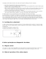
In the event of a fault resulting in the unlocking of the guard locking, this is detected by the solenoid interlock and the safety
gates Y1/Y2 switch off. When such a fault occurs the protection equipment may open immediately, just once, before the safe
condition of the machine is reached. The system reaction of category 2 allows that a fault can occur between tests causing the
loss of the safety function which is detected by the test.

2

The actuation of the interlock must be compared externally with the OSSD release. If a shut-down now occurs due to an
unintentional unlocking this is detected by an external diagnostic.

UL notice

]

This appliance is intended to be powered by a listed source of limited voltage, limited current or Class 2. This unit must be
supplied with at least 24 V DC and 0.8 A via a listed (CYJV) cable/connector assembly.

FCC/IC - Note

§

This device complies with Part 15 of the FCC Rules and contains licence-exempt transmitter/receivers that are compliant with
ISED (Innovation, Science and Economic Development) Canada licence-exempt RSS standard(s).
Operation is subject to the following two conditions:
(1) This device may not cause harmful interference, and
(2) This device must be able to tolerate interfering signals. This includes interfering signals that may cause the unit not to
function as desired.
This device complies with the nerve stimulation limits (ISED SPR-002) when operated at a minimum distance of 100 mm.
Changes or adjustments not expressly approved by K.A. Schmersal GmbH & Co. KG could void the user's authority to operate
the equipment.

3 Mounting

3.1 General mounting instructions

2

Please observe the remarks of the standards EN ISO 12100, EN ISO 14119 and EN ISO 14120.

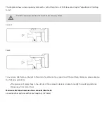
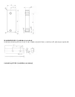
For the correct fixing of the solenoid interlock and the actuator, two mounting holes for M6 screws are provided
(tightening torque: 6 … 7 Nm).

Any mounting position. The system must only be operated with an angle of ≤ 2° between the solenoid interlock and the
actuator.

Содержание AZM300Z-I2-ST-1P2P-N-DU

Страница 1: ...e 3 3 Emergency exit T T8 or emergency release N 3 4 Mounting with mounting plate 3 5 Dimensions 3 6 Actuator and accessories 4 Electrical connection 4 1 General information for electrical connection...

Страница 2: ...ations regarding occupational safety and accident prevention prior to installation and putting the component into operation The machine builder must carefully select the harmonised standards to be com...

Страница 3: ...iption 1 5 General safety instructions The user must observe the safety instructions in this operating instructions manual the country specific installation standards as well as all prevailing safety...

Страница 4: ...is to be used marked with the symbol in the ordering code The actuator monitoring variant B is a safety switch with an interlock function for process protection The safety function consists of safely...

Страница 5: ...maintenance are observed 2 5 Exclusion of liability We shall accept no liability for damages and malfunctions resulting from defective mounting or failure to comply with the operating instructions ma...

Страница 6: ...Features Power to unlock Yes Solenoid interlock monitored Yes Latching Yes Emergency release Yes Short circuit detection Yes Cross circuit detection Yes Series wiring Yes Safety functions Yes Integral...

Страница 7: ...tching force adjustable position 2 50 N Type of the fixing screws 2x M6 Tightening torque of the fixing screws minimum 6 Nm Tightening torque of the fixing screws maximum 7 Nm Mechanical data Switchin...

Страница 8: ...Protection class III Permissible installation altitude above sea level maximum 2 000 m Ambient conditions Insulation values Rated insulation voltage U i 32 VDC Rated impulse withstand voltage U imp 0...

Страница 9: ...Switching thresholds 3 V 5 V Low 15 V 30 V High Current consumption at 24V 5 mA Test pulse duration maximum 1 ms Test pulse interval minimum 100 ms Classification ZVEI CB24I Sink C1 Classification ZVE...

Страница 10: ...X1 Safety input 1 PIN 3 A2 GND PIN 4 Y1 Safety output 1 PIN 5 OUT Diagnostic output PIN 6 X2 Safety input 2 PIN 7 Y2 Safety output 2 PIN 8 IN Solenoid control Note about the safety classification 2 Th...

Страница 11: ...must be supplied with at least 24 V DC and 0 8 A via a listed CYJV cable connector assembly FCC IC Note This device complies with Part 15 of the FCC Rules and contains licence exempt transmitter rece...

Страница 12: ...d be reduced Mounting of the solenoid interlock and the actuator Refer to the mounting instructions manual for the corresponding actuator 2 The actuator must be permanently fitted to the safety guards...

Страница 13: ...orrect False To avoid any interference inherent to this kind of system and any reduction of the switching distances please observe the following guidelines The presence of metal chips in the vicinity...

Страница 14: ...mm 3 2 Manual release For the machine set up the solenoid interlock can be unlocked in a de energised condition The solenoid interlock is unlocked by turning the manual release in the position qThe no...

Страница 15: ...fter completing commissioning 3 3 Emergency exit T T8 or emergency release N With variants that have both emergency exit and emergency release the red lever is loosely supplied Before first use mount...

Страница 16: ...at it should only be used in an emergency The label can be used that was included in the delivery To activate the emergency release turn the red lever in the direction of the arrow to the end stop The...

Страница 17: ...3 5 Dimensions All measurements in mm AZM300 T T8 and N Device with emergency exit or emergency release Emergency exit T Emergency release N...

Страница 18: ...Emergency exit T8 3 6 Actuator and accessories Actuator AZ AZM300 B1 not included in delivery Mounting plate MP AZ AZM300 1 available as accessory...

Страница 19: ...MS AZ AZM300 B1 1 available as accessory Aluminium protective plate as a cover for use on glass and plastic doors on machines with high design requirements Lockout tag SZ 200 1 available as accessory...

Страница 20: ...n cable release 4 Electrical connection 4 1 General information for electrical connection 2 The electrical connection may only be carried out by authorised personnel in a de energised condition The vo...

Страница 21: ...op on the cables and the current carrying capacity of the individual components F Accessories for the series wiring For convenient wiring and series wiring of SD components the SD junction boxes PFB S...

Страница 22: ...serial diagnostics connections are wired in series and connected to a SD Gateway for evaluation purposes The safety outputs of the first safety component are wired to the safety monitoring module The...

Страница 23: ...SD output 5 GY GY GY X2 Safety input 2 6 PK VT PK Y2 Safety output 2 7 BU RD VT IN Solenoid control SD input 8 RD PK OR Connecting cables with coupling female IP67 IP69 M12 8 pole 8 x 0 25 mm to DIN 4...

Страница 24: ...an unlimited number of times When a new actuator is taught the code which was applicable until that moment becomes invalid Subsequent to that an enabling inhibit will be active for ten minutes thus p...

Страница 25: ...it upstream is open Flashes 1 Hz Off On 6 4 Solenoid interlock with conventional diagnostic output The short circuit proof diagnostic output OUT can be used for central visualisation or control tasks...

Страница 26: ...be locked or fault Legend Safety guard open Safety guard closed Locking time Safety guard not locked or fault Safety guard locked Lock Unlock Evaluation of diagnostic output Power to unlock IN 0 Lock...

Страница 27: ...king impossible 0 V 24 V On Off Flashes 0 V 24 V 0 V Safety guard closed and locked 0 V 24 V On Off On 24 V 24 V 24 V Error warning1 0 V 24 V On Flashes 2 On 24 V1 24 V1 0 V Error 0 V 24 V 24 V 0 V On...

Страница 28: ...d as slave in an existing field bus system In this way the diagnostic signals can be evaluated by means of a PLC The necessary software for the integration of the SD Gateway is available for download...

Страница 29: ...be unlocked if e g the door pulls the turret out of its rest position beyond the set latching force This can occur if doors are heavily distorted or when pulling the door The solenoid interlock can o...

Страница 30: ...ns of replacement actuators 2 Damaged or defective components must be replaced 8 Disassembly and disposal 8 1 Disassembly The safety switchgear must be disassembled in a de energised condition only 8...

Отзывы: