


4
Operating instructions
Solenoid interlock
AZM 200
EN
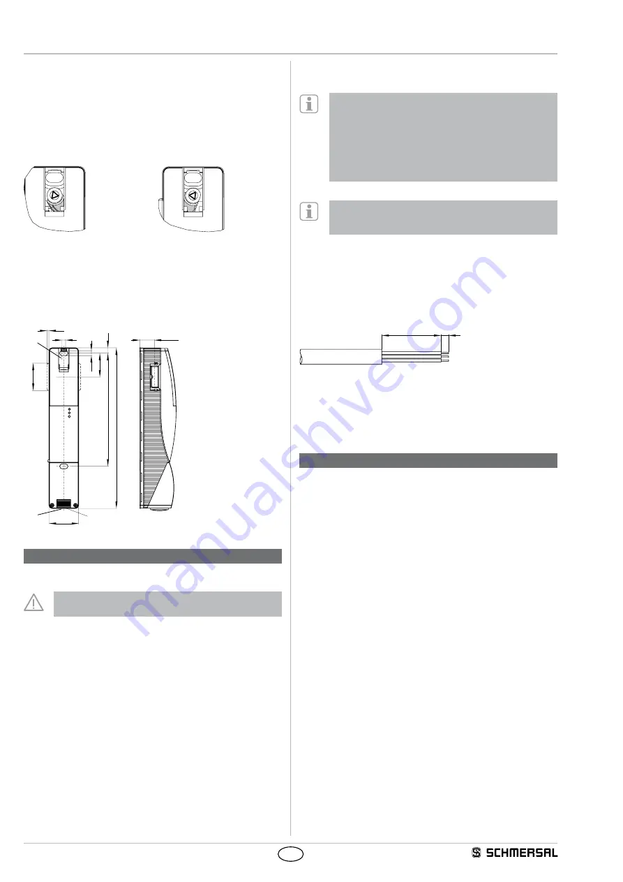
3.2 Manual release
For the machine set-up, the solenoid interlock can be unlocked in a
de-energised condition. After opening of the plastic flap "A" (refer to
image "Dimensions"), the triangular key must be turned clockwise
to bring the blocking bolt in unlocking condition. The normal locking
function is only restored after the triangular key has been returned to its
original position. Caution: do not turn beyond the latching point! After
being put into operation, the manual release must be secured by closing
the plastic flap "A" and affixing the seal, which is included in delivery.
Component ready
for operation
Component not ready
for operation
3.3 Dimensions
All measurements in mm.
40
220
155,5
5
6,5
32,5
38
7,5
M20x1,5
3,3
GN
RD
YE
20 1
±
A
B
Key
A: Manual release
B: Cable entry
4. Electrical connection
4.1 General information for electrical connection
The electrical connection may only be carried out by
authorised personnel in a de-energised condition.
The power supply for the solenoid interlock must provide protection
against permanent overvoltage. To that effect, stabilised PELV supply
units must be used. The safety outputs can be directly integrated in
the safety circuit of the control system. For applications up to PL e /
control category 4 to ISO 13849-1, the safety outputs of the solenoid
interlock(s) (max. 31 components (wired in series)) must be connected
to a safety-monitoring module of the same control category (refer to
wiring examples). Inductive loads (e.g. contactors, relays, etc.) are to
be provided with suitable interference suppression circuitry.
Requirements for the connected safety-monitoring module:
• Dual-channel safety input, suitable for 2 p-type semi-conductor outputs
Configuration of the safety controller
If the safety sensor is connected to electronic safety-
monitoring modules, we recommend that you set a
discrepancy time of 100 ms. The safety inputs of the safety-
monitoring module must be able to blank a test impulse of
approx. 1 ms. The safety-monitoring module does not need to
have a cross-wire short monitoring function, if necessary, the
cross-wire short monitoring function must be disabled.
Information for the selection of suitable safety-monitoring
modules can be found in the Schmersal catalogues or in the
online catalogue on the Internet: www.schmersal.net.
If the safety component is wired to relays or to non-safety relevant
control components, a new risk analysis must be carried out.
Cable
The cable entry is realised by a metric M20 gland. This gland must be
measured by the user so that it is suitable for the cable used. A cable
gland with strain relief and suitable IP protection class must be used.
40
5
The maximum cable length is 200 m (for ST2 M12 connectors approx.
20 m depending on the cable section used for an operating current
of 0.5 A). The maximum cable section is 1.5 mm², incl. conductuor
ferrules. Prior to the connection, the cable must be stripped by 40+5
mm and insulated by 5 mm. The fitted 24V, X1, X2 bridge is included in
the delivery of …-1P2P and …-SD2P.
5. Operating principle and diagnostic functions
5.1 Magnet control
In the power to unlock version of the AZM 200, the solenoid interlock
is unlocked when the IN signal (= 24V) is set. In the power to lock
version of the AZM 200, the solenoid interlock is locked when the IN
signal (= 24 V) is set.
5.2 Mode of operation of the safety outputs
In the standard AZM 200 variant, the unlocking of the solenoid interlock
causes the safety outputs to be disabled. The unlocked safety guard
can be relocked as long as the actuator is inserted in the AZM 200
solenoid interlock; in that case, the safety outputs are re-enabled.
The safety guard must not be opened.
In the B-variant AZM 200 B..., the opening of the safety guard causes
the safety outputs to be disabled.