background image


MVPHD-24 Operations Manual Version 0.9.0                                                                                               page 20 of 74 
October 26, 2020


Chapter 3


Operation 

Chapter 3 - Operation 


The MVPHD-24 is controlled by the front panel, or remotely by using DashBoard™ Control Software. 


Front Panel Control 


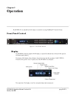
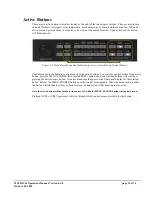
Figure 3-1. Front Panel Controls 


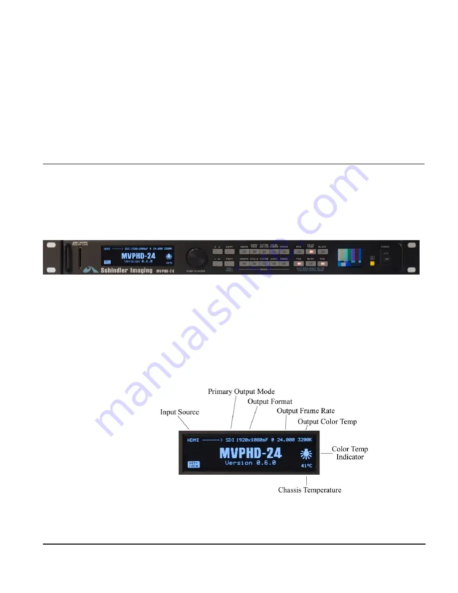
Display 


The MVPHD-24 utilizes a graphic OLED display to report status information, and to assist the operator 
while making adjustments. 


The top line of the display always indicates important status about the operation of the MVPHD-24. 


This allows the operator to see at a glance, how the MVPHD-24 is configured. 


The remainder of the display is used for various adjustment and status menus. 

Содержание CAL MEDIA MVPHD-24

Страница 1: ...g Inc MVPHD 24 Video Frame Rate Converter Preliminary Operations Manual Firmware version 0 9 0 Schindler Imaging a trademark of California Media Engineering Inc MVPHD 24 Operations Manual Version 0 9 0 October 26 2020 ...

Страница 2: ...of copyrighted software and firmware is prohibited Notice The material in this manual is furnished for informational use only It is subject to change without notice and should not be construed as a commitment by Cal Media Cal Media assumes no responsibility or liability for errors or inaccuracies that may appear in this manual Trademarks Schindler Imaging is a trademark of California Media Enginee...

Страница 3: ...n the equipment manual indicates a situation which if not avoided may result in major or minor equipment damage or a situation which could place the equipment in a non compliant operating state Notice This symbol is used to alert the user that an electrical or electronic device or assembly is susceptible to damage from an ESD event ESD Susceptibility Important Safety Instructions This product shou...

Страница 4: ... The equipment that you purchased required the extraction and use of natural resources for its production It may contain hazardous substances that could impact health and the environment To avoid the potential release of those substances into the environment and to diminish the need for the extraction of natural resources Cal Media encourages you to use the appropriate take back systems These syst...

Страница 5: ...el Control 20 Display 20 Controls 21 Control Menus 21 INPUTS 21 Menu Input Source 21 Menu Input YPbPr Level 21 Menu VGA Input Vert Position 22 Menu VGA Input Horz Position 22 Menu VGA Input Horz Adjust 22 Menu VGA Input Sample Phase 22 Menu Input Status 22 VIDEO PROC 23 Menu Proc Amp Enable 23 Menu Level Contrast 23 Menu Setup Brightness 23 Menu Chroma Color 23 Menu Hue Tint HUE MODE 23 Menu Y C D...

Страница 6: ...rtical Filter 31 Menu Update Firmware 31 Menu System Date Time 31 Menu Motion Filter 32 Menu 3 2 Cadence Detect 32 STILLS Still Image Buffers 32 Menu Capture Output to Buffer 32 Menu Load Buffer 1 from SD Card 33 Menu Load Buffer 2 from SD Card 33 Menu Load Buffer 3 from SD Card 33 Menu Load Buffer 4 from SD Card 33 Menu Save Output Image to SD Card 33 Menu Delete Image from SD Card 34 PRESETS 34 ...

Страница 7: ...Size Centering Controls 49 Level Proc Amp Controls 49 Sharpness 49 Color Temperature 50 MVPHD 24 s Color Temperature Process vs Standard Color Correction 50 Color Temp Enable 50 Output Color Temperature 50 Color Temp Adjust 50 Security cam Effect 50 Synchronization 51 MVPHD 24 as Master Reference 51 Single Film Camera as Reference 51 Genlocking No Need For Black Burst 51 Phasing the Camera s Shutt...

Страница 8: ...t Image to SD Card 59 Menu Delete Image from SD Card 59 Chapter 8 Adding Custom Test Signals 60 Introduction 60 Custom Key 60 Custom TSG Images 60 Custom TSG Signal Names 60 Capturing Custom TSG Images 60 Menu Capture Output to CustomTSG 61 Loading Custom TSG Images from SD Card 61 Menu Load CustomTSG1 from SD Card 61 Menu Load CustomTSG2 from SD Card 61 Menu Load CustomTSG3 from SD Card 61 Menu L...

Страница 9: ...nit solution to simplify the task of 24 frame playback Should you have a question pertaining to the installation or operation of your MVPHD 24 please contact us at the numbers listed on the back cover of this manual or through our web site at www calmedia com Overview The MVPHD 24 is the newest generation HD Video Up Down Frame rate Converter developed specifically for the 24 frame playback indust...

Страница 10: ...m SD MMC card Visual effects including freeze frame synchronized snow or MPEG blockiness dissolve Genlock to Frame Drive Vert drive HD tri level SD black burst or SDI input Genlock phase controls vertical 360 degree horizontal and subcarrier Genlock indicator LED on the front panel Audio channel mapping and level controls for embedded SDI and HDMI audio Dedicated EFX TSG Color Temp Monochrome Goto...

Страница 11: ...nectors VGA connects to VGA OUT HDMI connects to HDMI OUT SDI connects to SDI OUT Output Menus Press OUTPUT button to access output menus Press NEXT or PREV buttons to locate Primary Output Mode menu Use the Knob or buttons to select the type of output being used Composite YPbPr RGB SDI VGA or HDMI Once the primary output is selected push on the knob to enter selection The selected primary output ...

Страница 12: ...ti tap frame rate conversion is performed when changing frame rates and a secondary scaler is used to down convert the output video to composite Composite YC Component Inputs The analog video inputs use 3 multi purpose BNC connectors for either composite Y C signals or component signals These inputs accept standard NTSC or PAL video signals videotape machines video cameras tuners video disks video...

Страница 13: ...zing the image and adjusting the camera s shutter phase Up to eight user created full frame test signals may be added to the list of TSG signals Test signals are produced on the input path allowing it to be resized with the scaler Scaler Size and Centering Controls The scaler is used to automatically change the input resolution to match the output In addition Size and Centering controls allow the ...

Страница 14: ...s from SD to HD resolutions and graphic formats up to 1920x1080p VGA Outputs The VGA outputs produce standard VGA resolutions up to 1920x1080p CBVS Ref Outputs The Ref outputs can be individually configured to output various sync reference signals or composite video Outputs include composite video composite sync black burst tri level TTL composite sync TTL Vertical Drive and TTL Frame Drive For co...

Страница 15: ...eeding multiple output channels In addition to the SDI and HDMI inputs four internal tone generators and silence are available as sources Audio Levels and Phase FUTURE RELEASE The mapping function also provides individual level adjustment and phase control for all output channels The level of each channel may be adjusted 40 to 20 dB and the phase of each channel may be inverted 180 degree phase sh...

Страница 16: ...in the following note Static discharge can cause serious damage to sensitive semiconductor devices Avoid operating the device in high static environments such as carpeted areas and when wearing ESD synthetic fiber clothing Always exercise proper grounding Susceptibility precautions when operating the front panel or making connections to the device with other equipment Unpacking Unpack the MVPHD 24...

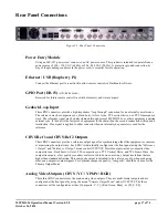
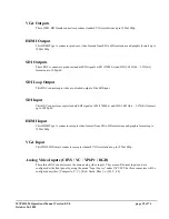
Страница 17: ... then the second connection will require a termination If no signal is applied to either connector then an internal sync generator is used for the reference CBVS Ref 1 and CBVS Ref 2 Outputs These BNC connectors provide a reference output signal for synchronizing other film equipment or cameras or monitoring the output video Each BNC is individually configured at the front panel using the Referenc...

Страница 18: ... clocked output of the SDI input SDI Input This BNC connector accepts standard SDI signals at SD 270Mb s and HD 1 485Gb s 2 97Gb s formats up to 1080p 60 HDMI Input This HDMI Type A connector accepts video formats from SD to HD resolutions and graphic formats up to 1920x1080p VGA Input This DB15 HD female connector accepts standard VGA resolutions up to 1920x1080p Analog Video Inputs CBVS YC YPbPr...

Страница 19: ...PHD 24 conforms to the FAT32 specification so firmware and still image files may be exchanged easily with most computers Installation Locate the SD MMC socket at the left side of the MVPHD 24 s front panel The SD or MMC card should be positioned with the corner notch pointing down Using gentle pressure carefully slide the memory card all the way into the socket until it clicks The memory card shou...

Страница 20: ...ntrol Figure 3 1 Front Panel Controls Display The MVPHD 24 utilizes a graphic OLED display to report status information and to assist the operator while making adjustments The top line of the display always indicates important status about the operation of the MVPHD 24 This allows the operator to see at a glance how the MVPHD 24 is configured The remainder of the display is used for various adjust...

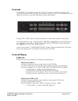
Страница 21: ...ar along the bottom of the menu In these cases pushing in on the rotary knob will activate the new selection Control Menus INPUTS This button is used to access menus for selecting and configuring inputs Menu Input Source This menu is used to select the video input source for the MVPHD 24 The current selected source is always shown at the top left corner of the front panel display Options are Compo...

Страница 22: ...ns to adjust the position in manual mode Menu VGA Input Horz Adjust This menu is used to adjust the horizontal width adjustment of the VGA input s capture window In auto mode default the MVPHD 24 automatically adjusts the width In manual mode the current adjustment value is indicated in BOLD on the second line See Chapter 7 for further discussion of the VGA capture window Push the knob to alternat...

Страница 23: ...58 to 58 with a default value of 0 Use the Knob or buttons to adjust Menu Chroma Color This menu is used to adjust the color saturation of the video inputs Range of adjustment is 0 to 200 with a default value of 100 Use the Knob or buttons to adjust Menu Hue Tint HUE MODE This menu is used to adjust the color hue or tint of the video inputs and select the hue mode Range of adjustment is 50 to 50 d...

Страница 24: ...of the video outputs active picture in the horizontal side to side direction This menu displays the size in both percent and number of pixels Use the buttons to adjust in 5 pixel increments Use the Knob to adjust in 1 pixel increments Menu Horz Center This menu is used to position the center of the video outputs active picture in the horizontal side to side direction Use the buttons to adjust in 5...

Страница 25: ...will appear stretched vertically or horizontally 16x9 4x3 16x9 Letter Box 4x3 16x9 4x3 Pillar Box Letter Pillar Box In this configuration black padding is added to the image to maintain the original aspect ratio For 16x9 to 4x3 black bars are added to the top and bottom to produce a letter boxed image For 4x3 to 16x9 black bars are added to the left and right sides to produce a pillar boxed image ...

Страница 26: ...ing the knob The top line indicates the color channel selected for adjustment Range of adjustment is 0 to 200 with a default value of 100 Push Knob to select color channel for adjustment Use the Knob rotate or to adjust Menu Output Gamma RGB This menu is used to adjust the red green and blue gamma of the output video signal Adjustments are made individually to the red RED green GRN or blue BLU cha...

Страница 27: ...e MVPHD 24 is not capable of producing perfect images on all outputs simultaneously Therefore the primary output mode is used to select the output that is most important The other outputs may continue to work but the quality may be degraded This setting affects what video formats are available For example VGA resolutions are only available when VGA is the selected output mode The selected primary ...

Страница 28: ...Drive and TTL Frame Drive When composite video is selected and the Primary Output Mode is not Composite then a low quality secondary scaler is used to down convert any output resolutions that are higher than standard definition This composite output is intended to be a reference only when producing other non composite output signals For optimum composite quality Composite should be chosen for the ...

Страница 29: ...the knob to enter selection If a signal is not present at the selected source the MVPHD 24 automatically goes into free run See the Genlock Status menu below for details of the selected signal The following controls adjust the timing of the video frame synchronizer Because of internal processing delays approx 3 lines a phase setting of zero clocks zero lines will guarantee one frame of delay in th...

Страница 30: ... This can occur if the MVPHD 24 s frame rate does not match the genlock source The second line of the status menu indicates the selected genlock source and a description of the signal detected BNC Input refers to the rear panel GENLOCK LOOP BNC connectors SDI Input refers to the serial digital SDI input The third line of the status menu indicates the lock status of both frequency Clk and Vertical ...

Страница 31: ... folder on the front panel of the MVPHD 24 see section Installation and Setup for details Press the and buttons together to begin the update The front panel display will show the progress of the update The update should complete in approximately 60 seconds Once the update has finished the MVPHD 24 will automatically re boot Note Some updates may require additional time to process new firmware file...

Страница 32: ... 59 94 60 Fps to 23 98 24 Fps Use the Knob rotate or buttons to select the desired mode Once the mode is selected push on the knob to enter selection STILLS Still Image Buffers This button is used to access the Still Image Buffer menus See Chapter 7 for detailed information on using the Still Image Buffers The MVPHD 24 contains four FLASH Still Image Buffers named Buffer 1 Buffer 2 Buffer 3 and Bu...

Страница 33: ...currently contained in the buffer is displayed in bold Use the Knob rotate or buttons to select desired still image Once selected push on the knob to load the still image Note any image can be effectively erased from a buffer by loading a blank image to that buffer blank may be selected by rotating the knob counter clockwise until it appears Blanking may be performed without a SD MMC Memory Card p...

Страница 34: ...Preset 1 Preset 2 Preset 3 and Preset 4 Selecting DEFAULT will overwrite all menus settings with factory default values Preset 1 4 are user created presets See below Use the Knob to select a preset Press and buttons simultaneously to recall preset Menu Store all Settings to This menu is used to store the current settings of all MVPHD 24 controls to a preset Each preset may be assigned a unique eig...

Страница 35: ...trol menus are available to configure each of the active buttons To access the control menus for an active button press the MENU ENABLE also labeled PREV button down and continue holding it down when pressing the desired active button A control menu should appear on the front panel display for the selected button Release the MENU ENABLE button once the control menu appears While the menu mode is a...

Страница 36: ...to adjust in 10 increments Use the Knob to adjust in 1 increments Menu EFX Transition Time This menu is used to set the time interval for the selected effect to transition from OFF to ON or ON to OFF The EFX indicator will flash during the transition Range of adjustment is 0 240 frames value ignored when Freeze Frame is the selected effect Use the buttons to adjust in 10 frame increments Use the K...

Страница 37: ...Step Luma and Chroma 10 Step 100 Ramp Luma and Chroma 100 Ramp 5 Shallow Ramp Digital Ramp Luma and Chroma Digital Ramp 75 Red Field 75 Green Field 75 Blue Field 50 Gray Field 75 Window 75 IRE 75 square 12 field pulse Window signal once every 12 fields F1 Blue F2 Yellow Alternating field signal F1 Blue F2 Yellow SMPTE Checkfield Digital Test custom test signal 1 see Chapter 8 for details custom te...

Страница 38: ...ee below Use the Knob or buttons to select a preset value Push knob to load preset Menu Color Temperature Adjust This menu is used to adjust the color temperature settings in the X and Y axis of the color circle COLOR CORRECT must be enabled for these settings to take effect See section 5 3 for more information Push Knob to toggle between X and Y adjustments Rotate the Knob or use buttons to adjus...

Страница 39: ...menus available for this function BLACK Go to Black This button when pressed alone will enable or disable Black mode When enabled the video outputs go to black level 0 IRE There are no menus available for this function FAN Chassis Fan Enable This button when pressed alone will enable or disable the chassis fan Pressing FAN while holding down the MENU ENABLE button will open the FAN control menu Me...

Страница 40: ...before communications with Dashboard begin When connected to a network DashBoard will identify the MVPHD 24 by its unique name MVPHD followed by the serial number If the MVPHD 24 is not visible click on the Dashboard s refresh button to search for new devices Click on the symbol next to the unique name Slot 0 MVPHD 24 will become visible Open the selected unit s control panel by right clicking on ...

Страница 41: ...utomatically detects the type of signal present The Genlock loop input provides a high impedance loop through connection for an external sync reference The reference signal may be daisy chained through several MVPHD 24s or other equipment requiring external sync If the unit is the last piece of equipment in the chain then the unused BNC will require a termination SDI Input This selection locks the...

Страница 42: ...or tips on using this feature Horiz Phase clocks This slider control is used to vary the horizontal phase of all the output signals from the MVPHD 24 including the sync reference outputs When genlocked this phase adjustment is with respect to the genlock source This control indicates the horizontal phase in video pixel clocks Subcarrier Phase deg This slider control is used to vary the subcarrier ...

Страница 43: ... video signal s brightness Use the Video Level control to adjust the video signal s contrast Use the Chroma control to adjust the video signal s color saturation Use the Hue control to adjust the video signal s color hue or chroma phase Use the Hue Mode control to select which method is used to calculate hue The Component Hue setting calculates the video hue based on equal scaling of the x y color...

Страница 44: ...rating condition of the MVPHD 24 Green indicates the MVPHD 24 is operating correctly Yellow indicates an unusual condition such as Loading Firmware Red indicates that a failure has been detected The Memory Card indicator displays the type of memory card installed Green indicates the memory card is working correctly Gray indicates no memory card detected The Genlock Status indicator shows the curre...

Страница 45: ...s is caused by the shutter s exposure time not equaling the video s scanning time Figure 4 1 below demonstrates this phenomenon SHUTTER OPEN OPEN TIME TOP BOTTOM TOP BOTTOM TOP BOTTOM TOP BOTTOM TOP BOTTOM SCANNED VIDEO IMAGES TOP BOTTOM RESULTING PICTURE TOP BOTTOM CLOSED CLOSED Figure 4 1 24 FPS Camera filming 30 FPS video As can be seen from figure 4 1 when the camera s shutter opens one and a ...

Страница 46: ... The film will be exposed with the bottom portion of image 1 and the top portion of image 2 This results in a picture where any objects in motion may be split in half The preceding example demonstrated a 90 degree phase difference between the shutter and the video image If the phase of the camera s shutter or the phase of the video image can be adjusted to bring these two into alignment or 0 degre...

Страница 47: ...degrees In this case a small portion of the image is never seen by the film thus leaving a black horizontal band in the picture It should be apparent that the larger the shutter angle differs from 180 degrees the larger this banding artifact is If the examples in figures 4 3 and 4 4 were aligned so that the shutter opening occurred at the top of the video image shutter phase equals 0 degrees then ...

Страница 48: ...h the shutter angle is greater than 180 degrees the area of the image that would be double exposed is now blanked The result is a perfect picture It should be noted that the blanking interval of a standard video image is approximately eight percent This means that the shutter angle must not differ from 180 degrees by more than the 8 percent 14 degrees or else a visible artifact will occur The phas...

Страница 49: ...rs having a digital locking circuit with no controls might not be able to lock at 24 FPS These monitors must be modified in order to be used Video Format Video Format The MVPHD 24 produces various output formats to feed to the monitor depending on what the monitor is capable of receiving Component YPbPr or RGB produces the best quality picture Y C SVHS produces a high quality picture Composite the...

Страница 50: ...and phases in a color circle The color circle uses X and Y coordinates to indicate the magnitude and phase of any color see vector scope image below In order to change the color temperature the MVPHD 24 s process adds a predefined color to the UV signal that is based on the luminance signal s amplitude This process has the advantage of maintaining brightness and saturation while changing the signa...

Страница 51: ...miscellaneous sync converter boxes Phasing the Camera s Shutter It is important to vertically phase the camera with the television monitors to eliminate any artifacts As described in Chapter 4 Overview of 24 FPS Playback even if the shutter angle is exactly 180 degrees there can still be motion splitting if the camera and monitor are not in alignment Traditionally the camera is phase aligned by lo...

Страница 52: ... one and yellow in field two Since the camera shutter sees only 50 of the picture with a 180 degrees shutter it will only see one of two fields When phased correctly the shutter will see either an all blue or an all yellow picture If the shutter phase is not correct there will be a split image that is part blue and part yellow SHUTTER OPEN TIME TOP BOTTOM SCANNED VIDEO IMAGES BOTTOM RESULTING PICT...

Страница 53: ...which is the maximum shutter angle before the second field image begins to be exposed TOP TOP BOTTOM TOP BOTTOM 300 ACTIVE LINES 655 300 BLANKING ACTIVE LINES 655 TOTAL LINES TOP BOTTOM TOP MINIMUM ANGLE MAXIMUM ANGLE Figure 5 3 Calculation of shutter angles for normal blanking Increasing the Shutter Angle by Resizing the Image Increasing the One method to get larger shutter angles is to increase ...

Страница 54: ... might not be sampled resulting in a cropped picture Because of the variations of input positions the MVPHD 24 employs a Capture Window and an AUTO positioning algorithm to accurately sample the image VGA Capture Window When a new signal is applied to the VGA input the MVPHD 24 analyzes the horizontal and vertical frequencies of the signal to determine what its resolution is Based on pre programme...

Страница 55: ...ng which filters the DAC outputs to produce a smooth linear signal see figure 7 2 Figure 7 1 Example of VGA stair step signal Figure 7 2 Example of Video linear signal Figure 7 1 Figure 7 2 Example of VGA stair step signal Example of Video linear signal Because of this stair step signal the position of each sample or sample phase is very important in producing a clear sharp image see figures 7 3 a...

Страница 56: ...ut signal The Universal Lock feature must determine the following parameters to achieve lock Horz Resolution It is first decided that the horizontal sampling will be 1920 pixels per line This value is chosen because it is the maximum resolution of the MVPHD 24 Horz Overscan Since the signal is unknown the horizontal position of the image cannot be determined To compensate the picture size is assum...

Страница 57: ...caler when converting from the input s format to the output s format The operator should keep this in mind when capturing the output image The resolution of the captured image will be determined by the MVPHD 24 s Output Format setting For best quality it is recommended that the Output Format is either set to the same resolution as the input source or that it is set to the maximum resolution of 108...

Страница 58: ...till image Note any Still Image can be effectively erased from a buffer by loading a blank image to that buffer blank may be selected by rotating the knob counter clockwise until it appears Blanking may be performed without a SD MMC Memory Card present Menu Load Buffer 2 from SD Card This menu is used to load a still image into Buffer 2 from the SD MMC memory card see above for more details Menu L...

Страница 59: ...the cursor is located Hint pushing on the knob will jump the selected character to either A a _ or 0 Press both and together to capture the output image and save it to the SD MMC Card with the suggested or edited name The MVPHD 24 can delete unwanted still images from a SD MMC Card This feature can be used to free up space on the SD MMC Card limit of 253 stills or to declutter the list of availabl...

Страница 60: ...m TSG Images The Custom TSG buffers can hold full frame full color images up to 1080p resolution These images can be captured from the output image of the MVPHD 24 or loaded from the SD MMC Card Custom TSG Signal Names The Custom TSG signal name that appears in the list of test signals is either specified when capturing the output image of the MVPHD 24 or is based on the image s filename when load...

Страница 61: ...ges to the Custom TSG buffers a SD MMC Card must be installed on the front panel which contains both the Custom Key and the STILLS folder both located in the root directory To access Custom TSG menus press the TSG button while holding down the MENU ENABLE also labeled PREV button This will open the TSG control menus Pressing NEXT or PREV previous will step through the TSG control menus Menu Load C...

Страница 62: ...older located on the SD MMC Card The Batch Load feature requires the desired stills to be renamed and stored in a folder named CUSTOM The filename extension must be changed from HD2 to TSn where n represents the Custom TSG number 1 8 For example an image file with the name My test signal HD2 is renamed to My test signal TS1 and stored in the CUSTOM folder on the SD MMC Card This Image file will be...

Страница 63: ...then proceed to load all the image files in the CUSTOM folder before the unit completes booting To restore the Sizing Charts back to default remove or rename the CUSTOM folder from the SD card Place the most recent update folder MVP cme on the root directory of the SD MMC Card Turn the MVPHD s power switch off The SD MMC Card must be installed on the front panel which contains both the Custom Key ...

Страница 64: ...no errors occur during the unzip process Once unzipped the firmware update should be a folder with a cme extension containing several files To update the MVPHD 24 using a MMC or SD memory card copy the entire folder to the memory card s root directory Note The MVPHD 24 can only have one folder with a cme extension If the memory card already has a cme folder from an earlier update then the earlier ...

Страница 65: ...the home screen without updating then repeat the firmware installation described above Internal Firmware Installation If the first attempt has failed or was interrupted the MVPHD 24 may not function correctly or even boot To install the firmware under these conditions an internal firmware installation may be required 1 Turn power off 2 Remove the top cover of the chassis 3 Copy the firmware cme fo...

Страница 66: ...ed to receive this file 5 Click Finish to begin installing the new firmware When the installation is complete Click OK The Upload Wizard will close and the MVPHD 24 will automatically reboot with the new firmware Verify that the new version numbers are displayed on the Dashboard control Product menu Note Some updates may require additional time for the initial reboot cycle approx 15 seconds WARNIN...

Страница 67: ...ing the file If the MVPHD 24 still does not properly operate after trying all suggestions contact customer support at support calmedia com Troubleshooting Dashboard Firmware Installation Use the following information if the firmware upload process has failed If the error message Selected file does not exist or Selected file is not a valid upload file are displayed in the Upload Failed dialog box s...

Страница 68: ...0 mVpp C B Pb BNC 75 VGA RGB 700 mVpp TTL Horz and Vert Sync VGA HD 15 Male 75 Pixel clock up to 170MHz VESA EDID version 1 3 Plug and Play GENLOCK 1 0 Vpp video 286 mVpp composite sync or GENLOCK 2 BNCs Hi Z loop External Ref 2 3 Vpp min 5 5 Vpp max Frame or Vertical Drive DIGITAL INPUTS SDI 800 mVpp SD HD 3G 270MHz 1 485GHz 2 97GHz SDI BNC 75 SD Auto EQ to 400 meters Belden 1694A HD Auto EQ to 2...

Страница 69: ...ATS interlaced 2 1 with user controlled active lines of video NTSC NT443 PAL M 23 976 FPS 15 752KHz 657 lines 24 000 FPS 15 720KHz 655 lines 25 000 FPS 15 625KHz 625 lines 29 970 FPS 15 734KHz 525 lines 30 000 FPS 15 750KHz 525 lines PAL SECAM PAL N 23 976 FPS 15 608KHz 651 lines 24 000 FPS 15 624KHz 651 lines 25 000 FPS 15 625KHz 625 lines 29 970 FPS 15 734KHz 525 lines 30 000 FPS 15 750KHz 525 l...

Страница 70: ...nt YRB RGB Outputs SD 4 x over sampling 10 bit DAC 4 2 2 54 MHz HD 2 x over sampling 10 bit DAC 4 2 2 148 5 MHz PROCESSING Internal sampling 4 2 2 10 bit per channel CBVS Input Processing Adaptive 3D COMB filter Full Frame TBC Accepts non interlace video games and Macrovision encoded sources De interlace Motion compensated adaptive de interlacer Frame rate conversion Progressive processing with 3 ...

Страница 71: ...Manual Version 0 8 5 page 71 of 74 October 26 2020 Appendix B Pinouts Appendix B Pinouts GPIO Pin out 1 GPIO1 9 GND 2 GPIO2 10 GND 3 GPIO3 11 SPARE 4 GPIO4 12 5v 500mA 5 GPIO5 13 SPARE 6 GPIO6 14 GND 7 GPIO7 15 GND 8 GPIO8 ...

Страница 72: ...fications to this product will immediately void the warranty California Media Engineering Inc shall not be responsible for incidental or consequential damages nor damage due to misuse or the use of any unauthorized attachment or modification nor damage by the use of an unspecified electrical circuit In no event shall California Media Engineering Inc be responsible or liable for any damages arising...

Страница 73: ...a Return Material Authorization number RMA will be issued to you as well as specific shipping instructions Do not return any product before obtaining a RMA number Any shipping costs incurred are the customer s responsibility If available a temporary replacement unit may be provided at a nominal charge Cal Media s Technical Support Department will continue to provide advice on any product manufactu...

Страница 74: ...California Media Engineering Inc Voice 805 931 0857 info calmedia com support calmedia com ...

Отзывы: