


Commissioning
©
by Antriebs- & Regeltechnik Schimpf GmbH
13
Commissioning
Important:
The “Safety instructions for installation and maintenance” and the
“Safety instructions for commissioning” provided in this
document must be observed during the commissioning phase.
Installation
The drive must be firmly screwed to the fitting to be moved using the available threaded
holes on the flange plate. The drive shaft has a square socket as standard. The
arrangement and size of the threaded holes as well as the square socket can be found
in the
and
document.
Adapters for other shaft designs are also available. An overview of the standard
adapters can also be found in the
at the end of this document.
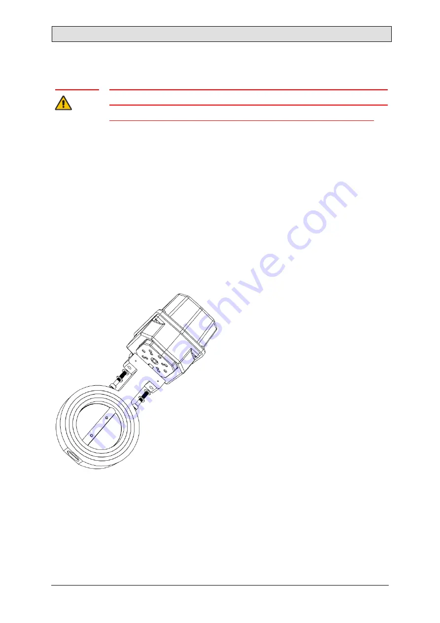
Installing a Schimpf control valve
To mount a Schimpf drive on a Schimpf
control valve, insert the square spindle at
end of the valve shaft into the square
socket of the drive. Make sure that the
square socket of the drive and the square
spindle of the valve are the same size.
The valve is fixed in place using the two
hexagon socket screws supplied with the
valve. When installing, make sure that the
drive is in the correct position relative to
the valve (open or closed).
Specialised shafts and adapter sets for other valves are available on request.
Содержание 00-10/30 STEP
Страница 28: ...Connections by Antriebs Regeltechnik Schimpf GmbH 28 Figure 10 CPU board 00 15 Figure 11 Add on board 00 15 ...
Страница 69: ...Declaration of Conformity by Antriebs Regeltechnik Schimpf GmbH 69 Declaration of Conformity ...
Страница 71: ...Dimensional drawing by Antriebs Regeltechnik Schimpf GmbH 71 Figure 15 Dimensions of drive type 00 15 ...
Страница 72: ...Dimensional drawing by Antriebs Regeltechnik Schimpf GmbH 72 Figure 16 Dimensions of drive type 01 15 ...