Application Notes
P746/EN AP/G31
MiCOM P746
(AP) 6-
53
AP
11.2.2
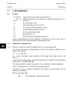
CT Specification according to IEC 185, 44-6 and BS 3938 (British Standard)
1.
Class X according to British Standard: Minimum knee point voltage for saturation
V
k
min = secondary I
F
max x (R
CT
+ R
B
)
With
secondary
I
F
max not less than 20 (if I
F
max < 20 In then I
F
max = 20)
Note:
This specification is valid for external faults.
This provides a sufficient margin of security for CT saturation immunity.
2.
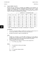
Class 5P to IEC 185. Conversion of class X (BS) with the 5P equivalent (IEC)
3.
Class TPX and TPY according to IEC 44-6. IEC defines a composite error as a
percentage of a multiple of the rated current (
I
N
) on a definite load SVA.
e.g.
CT 1000/5 A – 50VA 5P 20 [CT
I
np
/
I
n
A – SVA Accuracy P Kscc]
This definition indicates that the composite error must be lower than 5%, for a primary
current of 20
I
np
when the external load is equal to 2 ohms (50VA to
I
n
). If secondary
resistance, R
CT
, is known it is easy to calculate the magnetising EMF developed with the
fault current (20
I
n
). Actually if the error is 5% (= 5A) with this EMF, the point of operation is
beyond the knee point voltage for saturation. By convention one admits that the knee point
voltage, V
k
, is 80% of this value. For a conversion between a class 5P (IEC) and a class X
(BS) CT one uses the relation:
V
k
=0.8 X [(SVA x K
ssc
)/
I
n
+ (R
CT
x K
ssc
x
I
n
) ]
SVA = (
I
n
x V
k
/0.8 K
ssc
) – R
CT
x
I
n
2
In particular cases, calculation could reveal values too low to correspond to industrial
standards. In this case the minima will be: SVA min = 10 VA 5P 20 which correspond to a
knee point voltage of approximately V
kmin
= 70 V at 5A or 350V at 1A. Class TPY would
permit lower values of power, (demagnetisation air-gap). Taking into account the weak
requirements of class X or TPX one can keep specifications common.
For accuracy, class X or class 5P current transformers (CTs) are strongly recommended.
The knee point voltage of the CTs should comply with the minimum requirements of the
formulae shown below.
V
k
≥
k
(R
CT
+ R
B
)
Where:
V
k
=
Required knee point voltage
k = Dimensioning
factor
R
CT
=
CT secondary resistance
R
L
=
Circuit resistance from CT to relay
R
B
=
Burden
resistance
k is a constant depending on:
I
f
=
Maximum value of through fault current for stability (multiple of
I
n)
X/R =
Primary system X/R ratio (for the P746 system, X/R up to 120)
The following CT requirement can be developed for the P746 scheme
V
k
>
secondary
I
f max x (R
CT
+ R
B
)
With R
B
= 2 R
L
Содержание MiCOM P746
Страница 4: ......
Страница 5: ...Pxxx EN SS G11 SAFETY SECTION...
Страница 6: ......
Страница 8: ...Pxxx EN SS G11 Page 2 8 Safety Section BLANK PAGE...
Страница 16: ...P746 EN IT G31 Introduction MiCOM P746...
Страница 18: ...P746 EN IT G31 Introduction IT 1 2 MiCOM P746 IT BLANK PAGE...
Страница 26: ...P746 EN TD G31 Technical Data MiCOM P746...
Страница 38: ...P746 EN GS G31 Getting Started MiCOM P746...
Страница 78: ...P746 EN ST G31 Getting Started MiCOM P746...
Страница 80: ...P746 EN ST G31 Settings ST 4 2 MiCOM P746 ST BLANK PAGE...
Страница 112: ...P746 EN ST G31 Settings ST 4 34 MiCOM P746 ST BLANK PAGE...
Страница 114: ...P746 EN OP G31 Operation MiCOM P746...
Страница 136: ...P746 EN OP G31 Operation OP 5 22 MiCOM P746 OP BLANK PAGE...
Страница 138: ...P746 EN AP G31 Application Notes MiCOM P746...
Страница 142: ...P746 EN AP G31 Application Notes AP 6 4 MiCOM P746 AP BLANK PAGE...
Страница 194: ...P746 EN AP G31 Application Notes AP 6 56 MiCOM P746 AP BLANK PAGE...
Страница 196: ...P746 EN PL G31 Programmable Logic MiCOM P746...
Страница 238: ...P746 EN MR A11 Measurements and Recording MiCOM P746...
Страница 240: ...P746 EN MR A11 Measurements and Recording MR 8 2 MiCOM P746 MR BLANK PAGE...
Страница 258: ...P746 EN FD G31 Firmware Design MiCOM P746...
Страница 280: ......
Страница 342: ...P746 EN CM F21 Commissioning and Maintenance CM 10 62 MiCOM P746 CM Commissioning Engineer Customer Witness Date Date...
Страница 348: ...P746 EN MT A11 Maintenance MiCOM P746...
Страница 350: ...P746 EN MT A11 Maintenance MT 11 2 MiCOM P746 MT BLANK PAGE...
Страница 364: ...P746 EN MT A11 Maintenance MT 11 16 MiCOM P746 MT BLANK PAGE...
Страница 366: ...P746 EN TS G31 Troubleshooting MiCOM P746...
Страница 368: ...P746 EN TS G31 Troubleshooting TS 12 2 MiCOM P746 TS BLANK PAGE...
Страница 382: ...P746 EN SC G31 SCADA Communications MiCOM P746...
Страница 424: ...P746 EN SC G31 SCADA Communications SC 13 42 MiCOM P746 SC BLANK PAGE...
Страница 426: ...P746 EN SG F21 Symbols and Glossary MiCOM P746...
Страница 438: ......
Страница 440: ...P746 EN IN G31 Installation IN 15 2 MiCOM P746 IN BLANK PAGE...
Страница 465: ...Installation P746 EN IN G31 MiCOM P746 IN 15 27 IN 10P74611 1 FIGURE 18 MiCOM P746 80TE WIRING DESCRIPTION P746xxxL...
Страница 468: ......
Страница 470: ...P746 EN HI G31 Remote HMI HI 16 2 MiCOM P746 HI BLANK PAGE...
Страница 500: ...P746 EN HI G31 Remote HMI HI 16 32 MiCOM P746 HI BLANK PAGE...
Страница 502: ......
Страница 504: ...P746 EN CS A11G31 Cyber Security CS 17 2 MiCOM P746 CS BLANK PAGE...
Страница 524: ...P746 EN VH G31 Firmware and Service Manual Version History MiCOM P746...
Страница 529: ......


